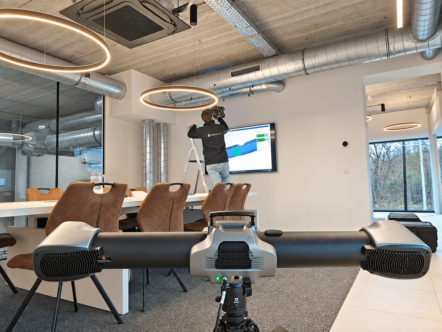
Anyone who stops by for a demo is literally sitting underneath this setup. The ventilation system in our conference room in Boutersem is a typical network of pipes: long, suspended from the ceiling, with branches, reducers, clamping rings, and a cable tray running right through it. It’s exactly the kind of geometry that would easily take hours to measure using traditional methods.
We scanned the entire system, which was about 5 meters long, using the TrackScan Sharp-S from Scanology. The actual scanning took about 30 minutes, with an accuracy of approximately 0.2 mm.
Project overview
| Object | Ventilation system in the TetraVision conference room (Boutersem) |
| Dimensions | Approx. 5 meters |
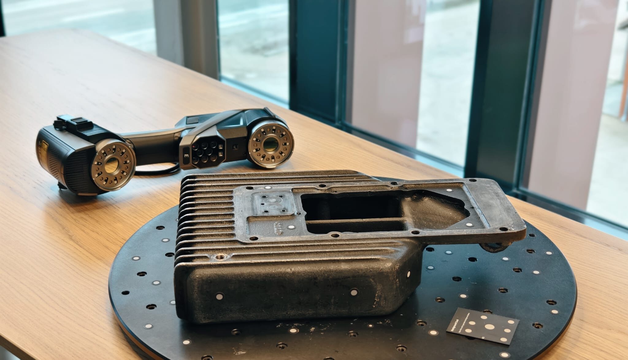
| Scanner | Scanology TrackScan Sharp-S, tracking 3D scanner |
| Software | Scanology DefinSight (scanning, alignment, and meshing) |
| Lineup | 2 tracker positions with overlap |
| Preparation | No scanning spray, no reference markers |
| Accuracy | Approx. 0.2 mm |
| Scan time | About 30 minutes |
| Output | High-quality mesh in STL format |
The challenge: mapping out the piping system as it actually is
Pipelines and pipe structures are rarely exactly as they appear on drawings. At some point, something was added, modified, or welded differently than planned. Anyone who wants to design a modification or expansion therefore needs to know the actual situation, not the theoretical one.
These types of objects are particularly difficult to measure. They are long, often hang high, and have many curved, smooth surfaces. With a traditional handheld scanner, this usually means applying hundreds of reference markers, matting the surface with scanning spray, and scanning in many small sections. That takes time, and errors are more likely to creep in over long lengths.
Our approach
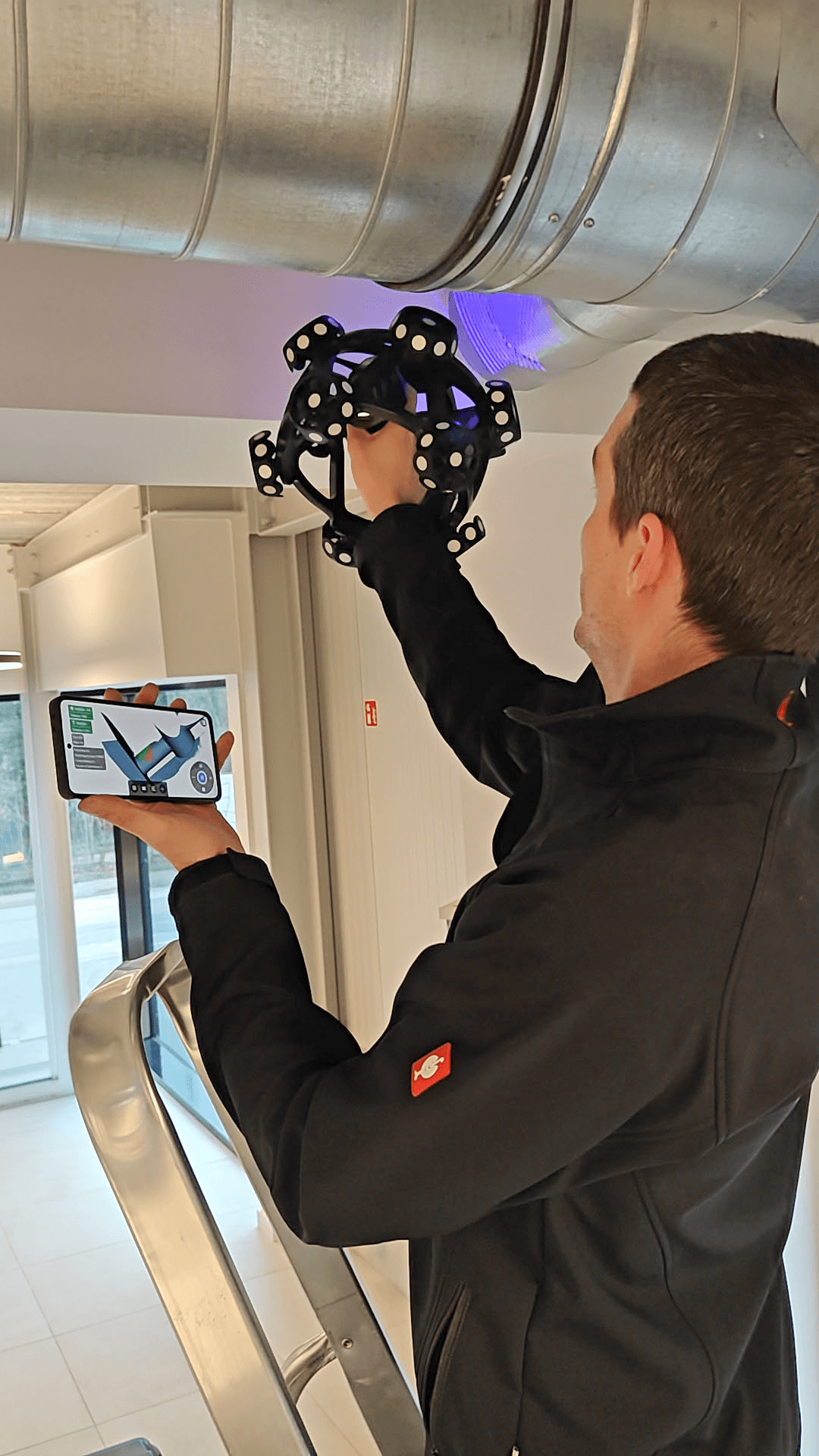
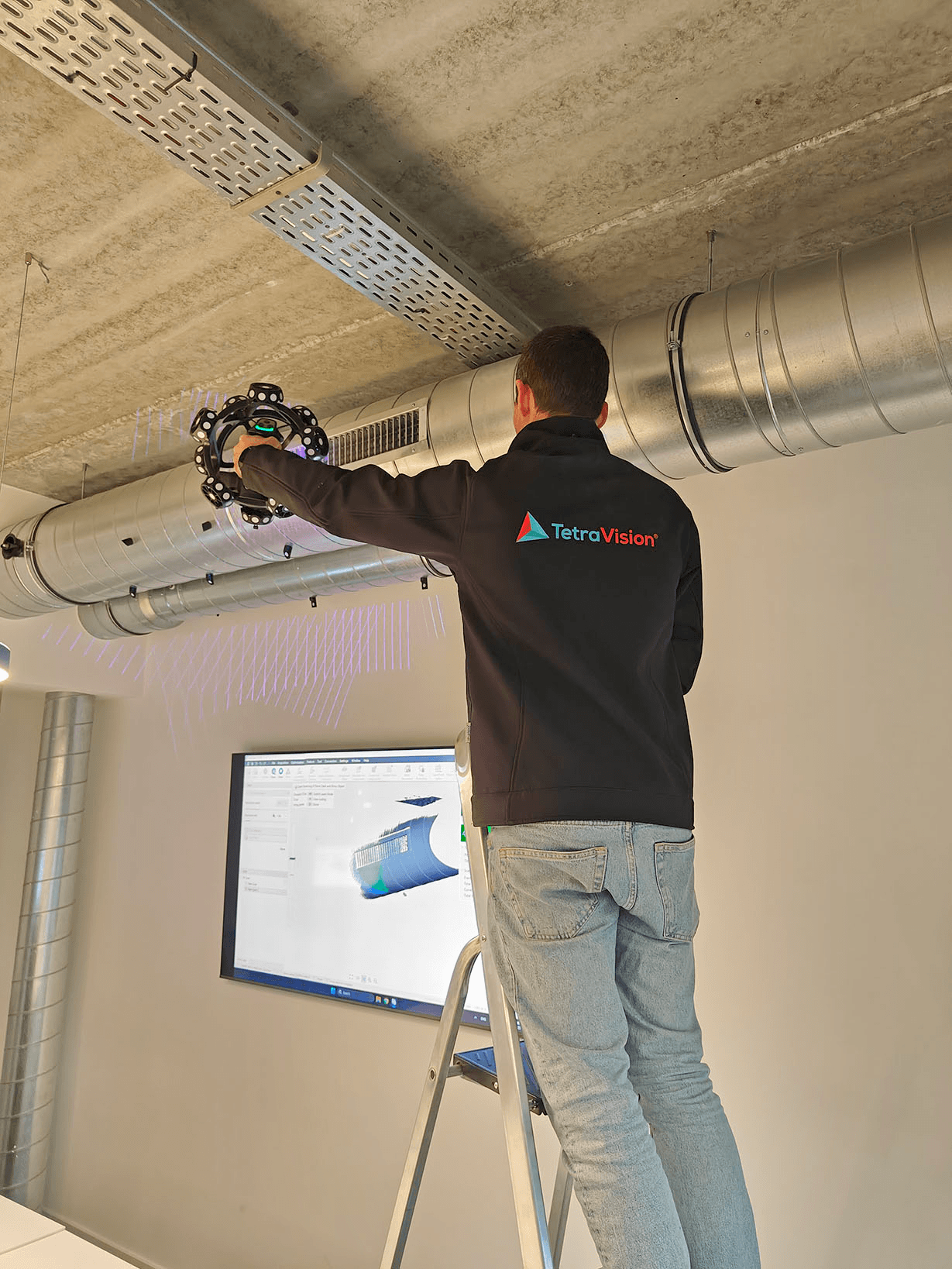
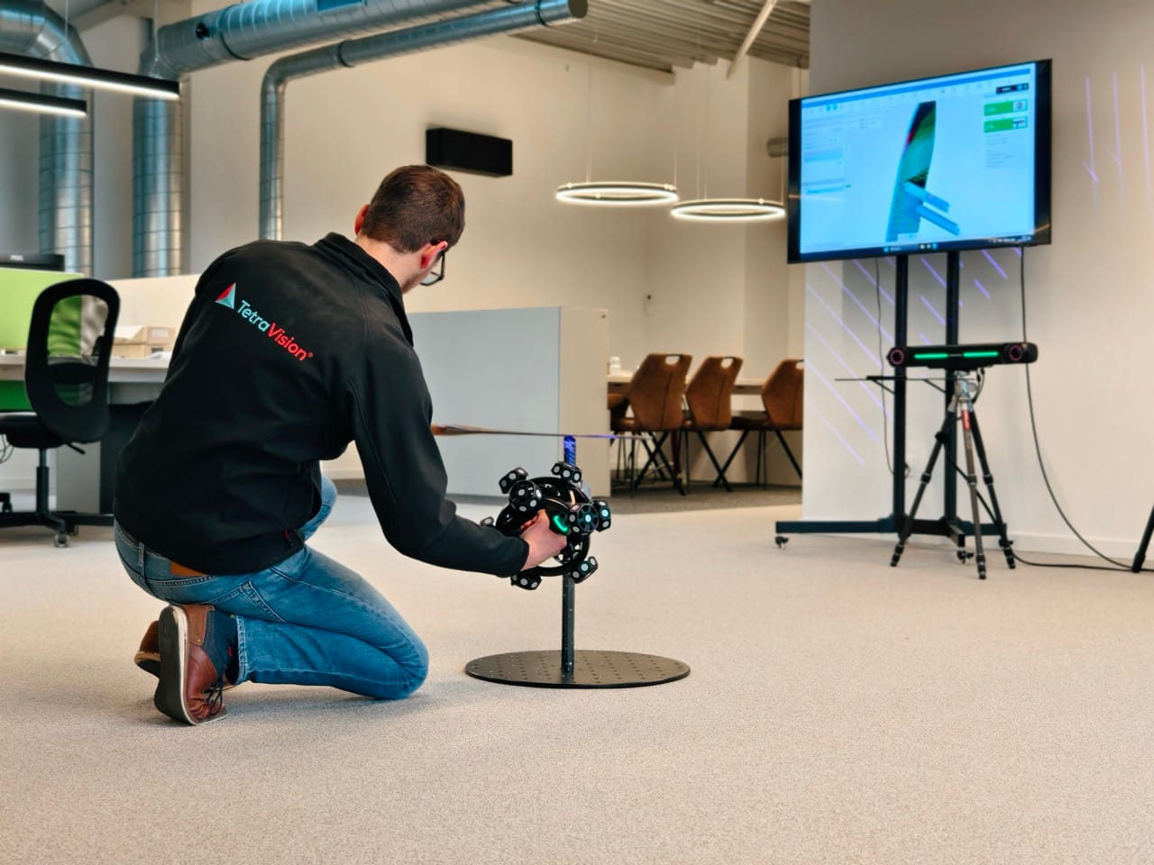
The TrackScan Sharp-S works with an external tracker that tracks the scanner’s position in space. That tracker has a tracking range of up to 8.5 meters and a measurement range of 135 m³. As a result, you don’t need to mark the object yourself.
- Set up and warm up. We positioned the tracker so that a large portion of the piping was visible at once. We then let the system warm up for half an hour to ensure a stable reading.
- Calibration. The tracker and scanner were calibrated in about five minutes.
- Scanning from two tracker positions. You aim the tracker and start scanning. No spray, no markers, just move the scanner along the piping. For the areas that weren’t visible from the first position, we moved the tracker once, ensuring sufficient overlap between the two scans.
- Alignment and meshing in DefinSight. In DefinSight, Scanology’s software, both point clouds were aligned using best-fit and merged into a single high-quality mesh in STL format. The entire process took less than 5 minutes.
How long does something like that really take?
| Set up the system | About 10 minutes |
| Warm up | About 30 minutes (ideally) |
| Calibration of the tracker and scanner | About 5 minutes |
| Scanning | About 30 minutes |
| Align, merge, and mesh | Less than 5 minutes |
| Packing | About 10 minutes |
The scanning time depends heavily on how much detail you need. The main point is that you can collect a great deal of useful data in a short amount of time.
How accurate is accurate enough?
We scanned this piping with an accuracy of approximately 0.2 mm. Whether that is sufficient always depends on the application and the associated tolerances. Our rule of thumb: the scanning system must achieve at least one-third of the required tolerance, or better.
For piping, tolerances are usually in the range of a few millimeters. So we’re well within that range here. In industry, building scanners are often used for this type of work, and they typically measure with an accuracy of around 2 mm. If your application requires greater precision, a tracking 3D scanner like the TrackScan Sharp-S will be about ten times more accurate.
The results
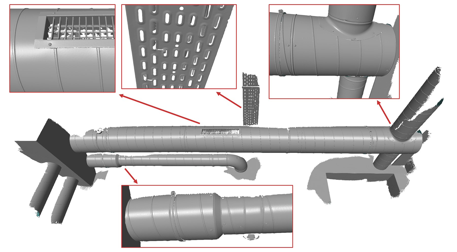
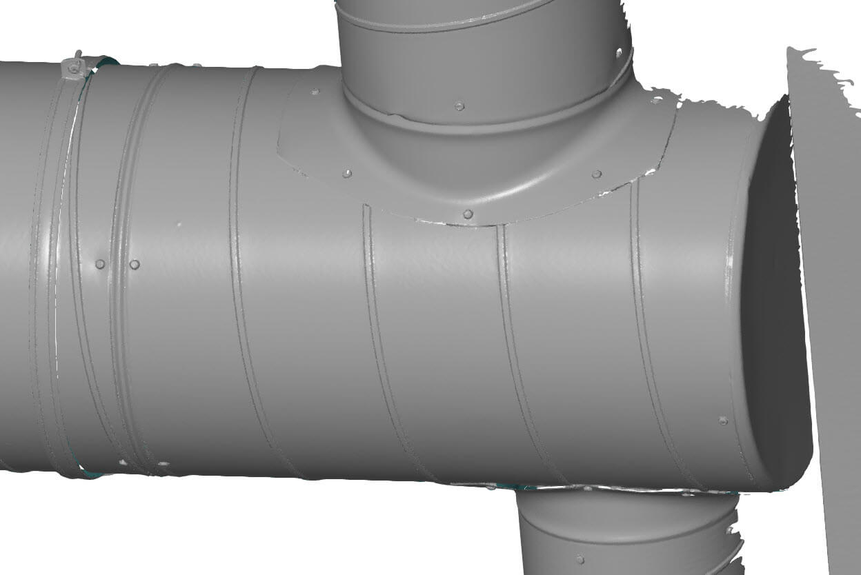
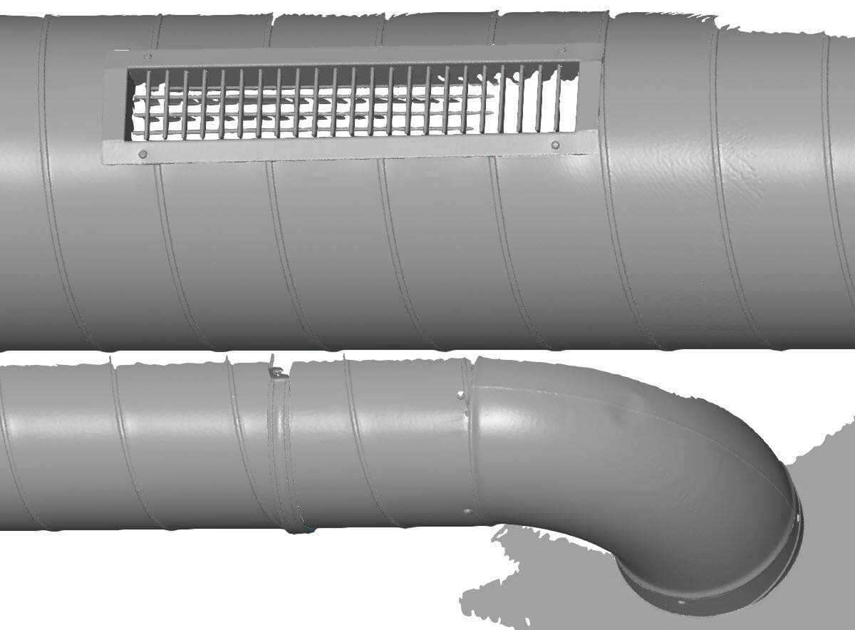
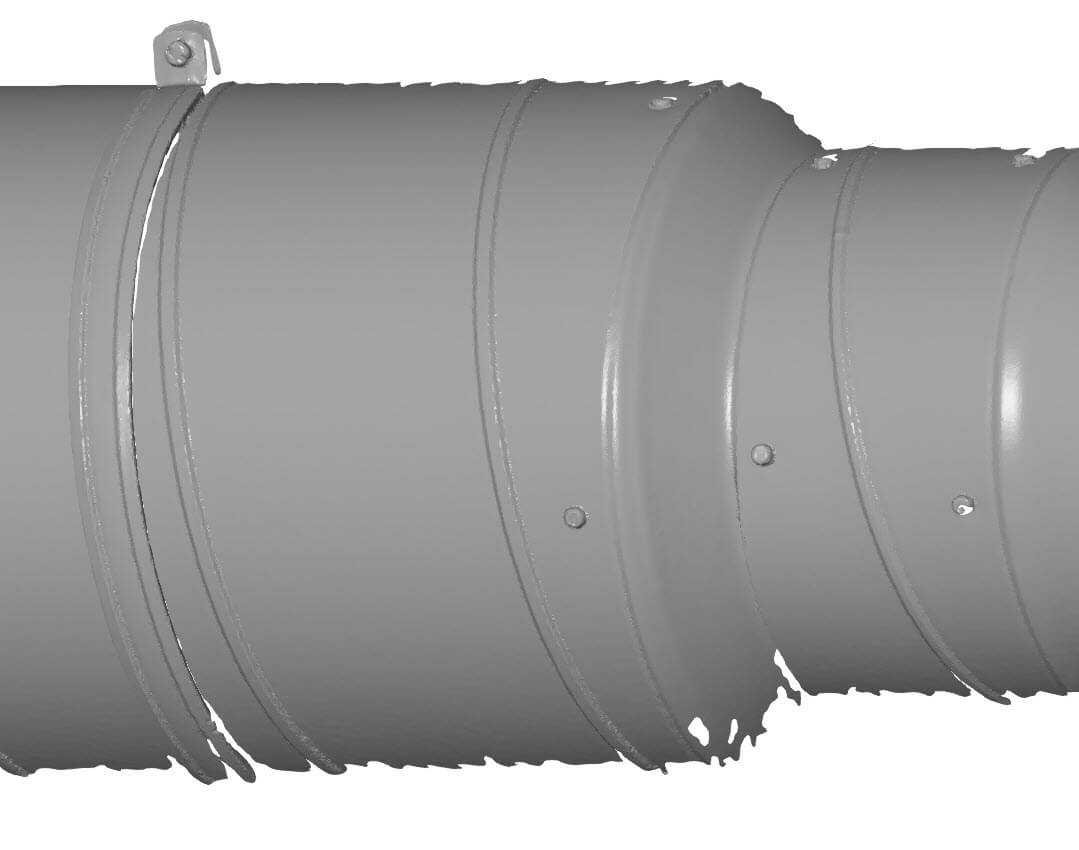
The result is a fully digital model of the ventilation system. Even the smallest details are included: the grille in the duct, the slots in the perforated cable tray, the clamping rings, and the transitions between different pipe diameters. You can see this in the detailed close-ups on the cover image.
Typically, you’ll process that mesh for piping in reverse engineering software such as QuickSurface, or directly in your CAD package. If you already work with SolidWorks, the QuickSurface for SOLIDWORKS add-in is the ideal tool: you can convert the scan into a CAD model without leaving SolidWorks.
Why this is relevant to the industry
We don’t scan ventilation ducts very often ourselves. We do, however, scan welded pipe structures in production environments. The goal is always the same: to accurately document the existing situation so that modifications or expansions can be designed to fit perfectly.
This enables a “first-time-right” approach. New parts fit during the initial installation, and machines or systems aren’t idle any longer than necessary. Examples of applications include:
- petrochemicals, oil, and gas
- pharmaceuticals and food industry
- water management
- metallurgy
- paper industry
Want to experience it for yourself?
Want to see how fast this goes, or are you unsure which scanner is right for your application? Stop by for a demo in Boutersem, and we’ll scan together. We’d be happy to show you the results of this project live—the piping will be right above your head.
Would you rather we do it for you? With our 3D scanning service, we can also scan at your location using various mobile scanners, ranging from small handheld devices to large tracking systems. And if you need a CAD model, we’ll help you with reverse engineering.
Request a demo or a quote. We always respond within 24 hours.