- From physical product to CAD design
Reverse Engineering
Reverse engineering is the process by which we will first digitize a physical object through 3D scanning and then convert it to a CAD model or a solid body in the form of a step, iges or parasolid file.
General
For the conversion from scan to CAD, we use specialized reverse engineering software. This is the link between 3D scanning and traditional CAD software (Solidworks, Siemens NX, Catia, etc.).
Over the years, we have built a systematic approach so that you always receive a quality CAD model that is useful for your application, and where you also have a clear picture of the differences between this model and the original scan. Below is an overview of our typical workflow for reverse engineering.
STEP 1: Calibration
Before we can start the actual scanning work, the scanner needs to be calibrated.
- The calibration panel is placed in front of the scanner within the specified distance. Meanwhile, proper lighting conditions and setup stability are checked.
- Warming up the scanner is necessary to ensure consistent operation.
- Once this is done, the calibration routine can be performed.
- The calibration is followed by a verification step to check that the scanner is correctly aligned and provides sufficient accuracy.
- If necessary, recalibration is performed.
Calibration is necessary to make accurate and reliable measurements, which is obviously essential. This also ensures consistency between scans, allowing for accurate comparisons and analysis of data sets.
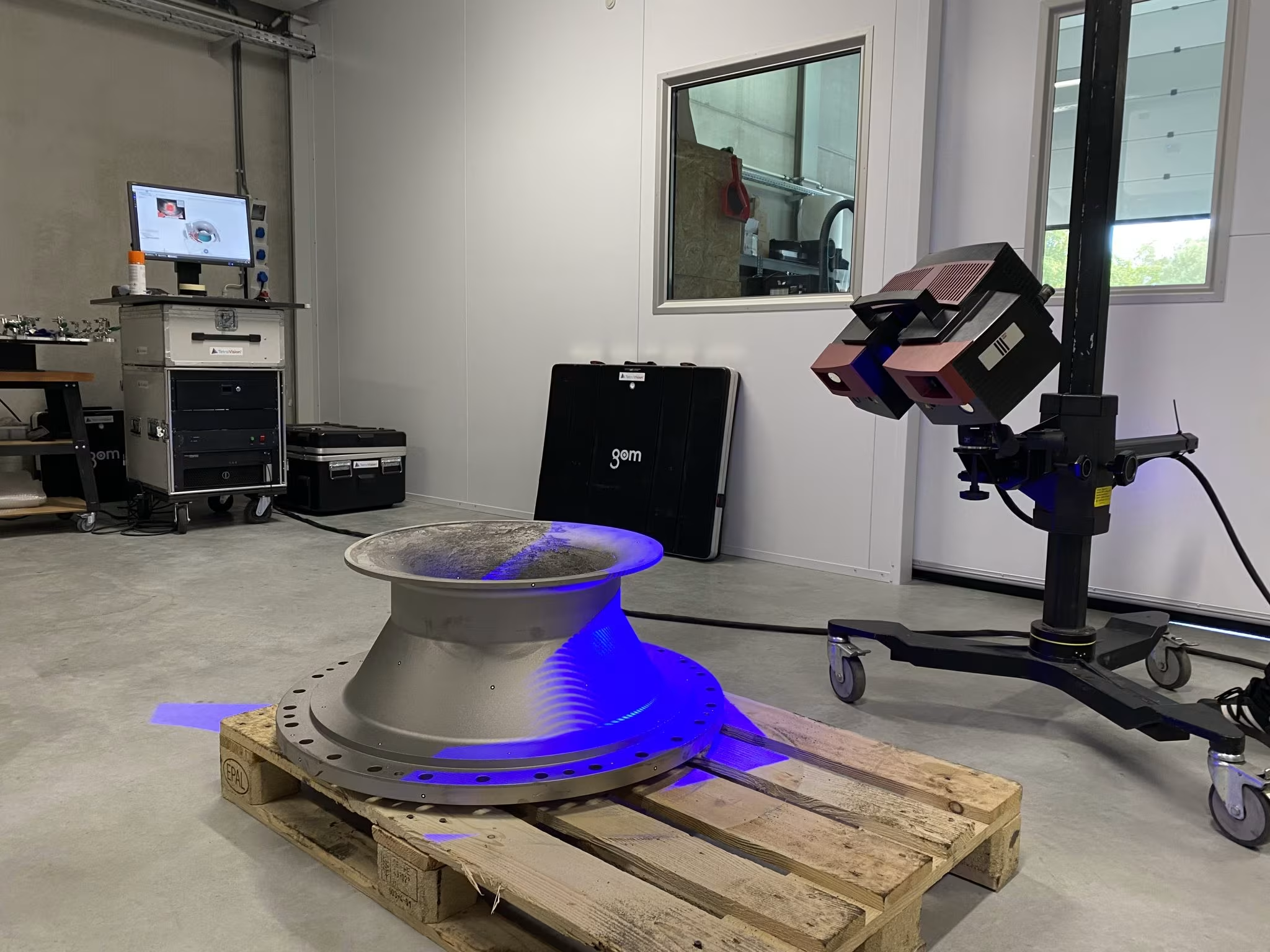
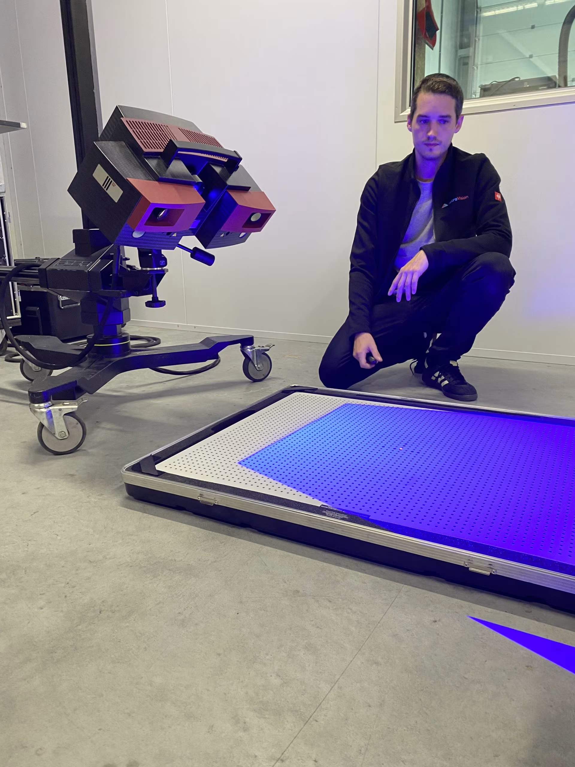
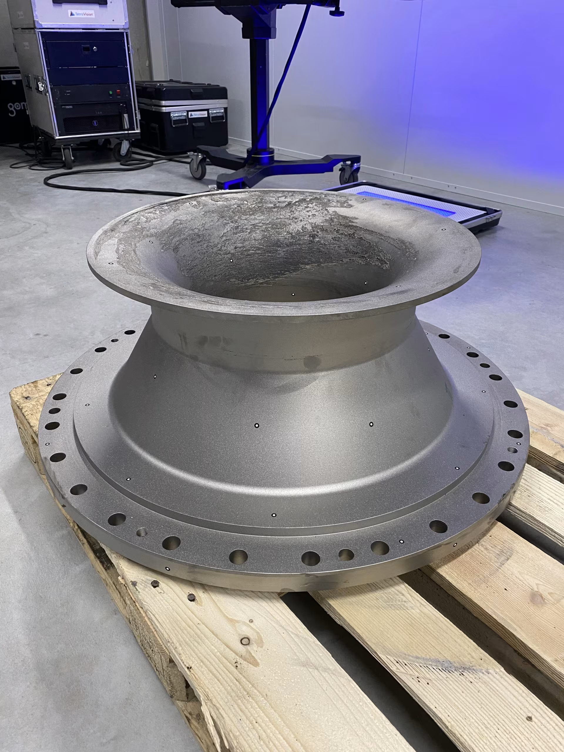
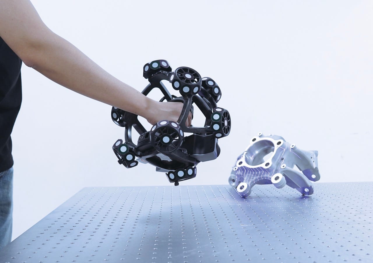
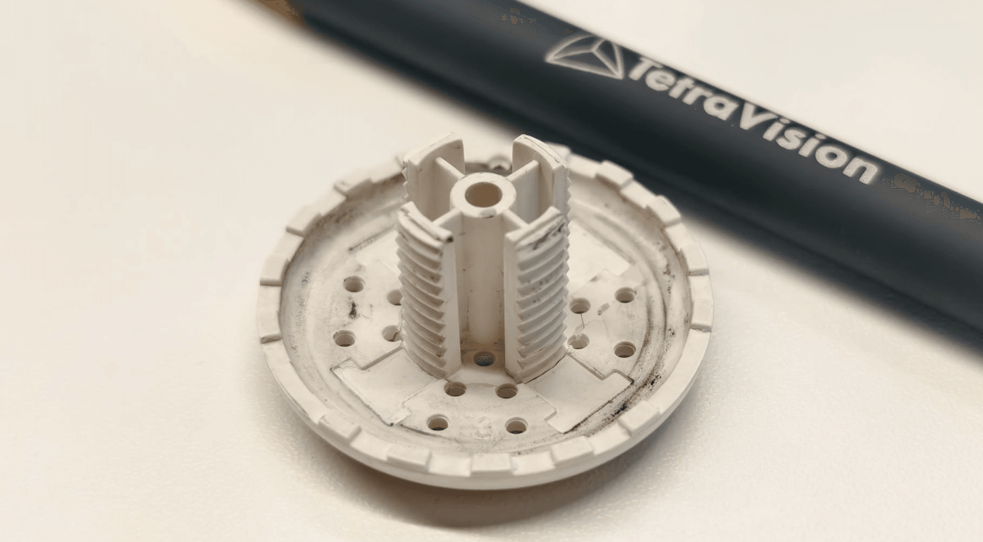
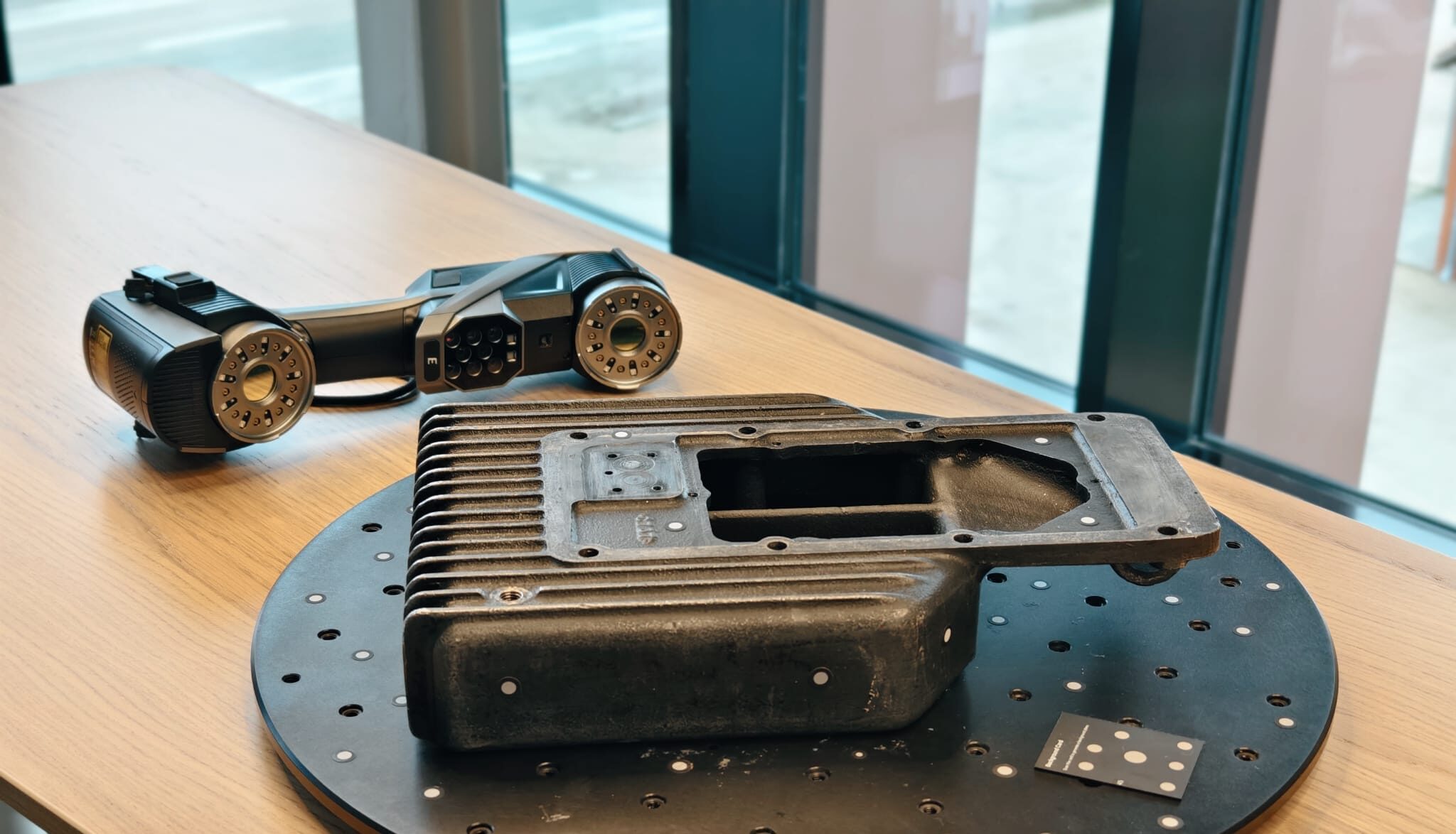
STEP 2: 3D Scanning
After calibration, we start digitally capturing the geometry of the physical object using a 3D scanner. This scanner creates a point cloud, a dense collection of data points that represent the surface of the object.
Depending on the part to be scanned, we use our blue light scanner, with or without photogrammetry, or the X-ray CT scanner.
The goal is to obtain an accurate representation of the object’s dimensions, shape and surface features. The result is then a rough point cloud or mesh model.
STEP 3: Data cleaning and processing
The point cloud data collected during scanning often contains noise or errors, such as overlapping points or unwanted artifacts. This step involves cleaning and refining the data to ensure accuracy. In this process, we engage:
- Remove unnecessary points or noise.
- Closing gaps in scan data.
- Optimize the mesh by reducing the number of polygons without losing details.
- Align the dataset in the global co-ordinate system.
The result is a high-quality mesh model ready for further processing.
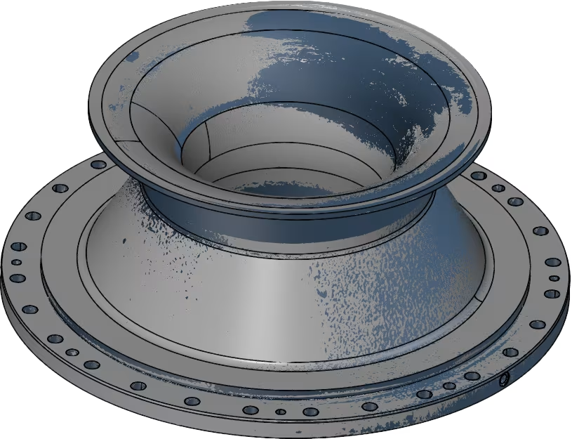
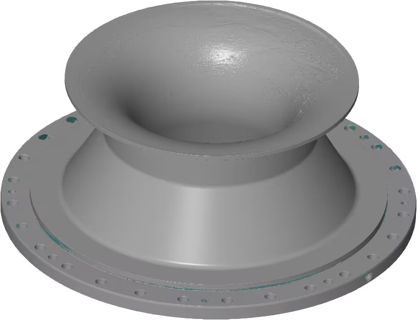
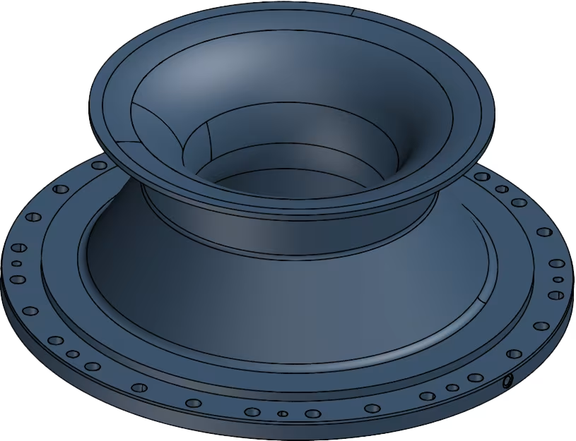
STEP 4: Conversion from Mesh to CAD
The next step is to convert the mesh model into a Computer-Aided Design (CAD) model. This is done using reverse engineering software.
Step by step, we will divide the mesh into its different main shapes in order to model it according to the traditional CAD operations (sketching, extrusion, rotation, boolean…) We try to work as much as possible according to the general design principles (perpendicularity, concentricity…) without deviating too much from the original scan.
When standard prismatic shapes (planes, cylinders…) are not sufficient we start using nurbs surfaces (free-form surfaces) or a combination of both.
The result is a CAD file (E.g. STEP, IGES or parasolid file) suitable for further machining or production.
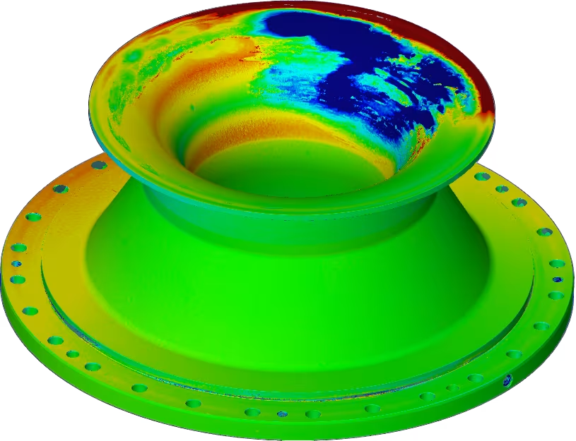
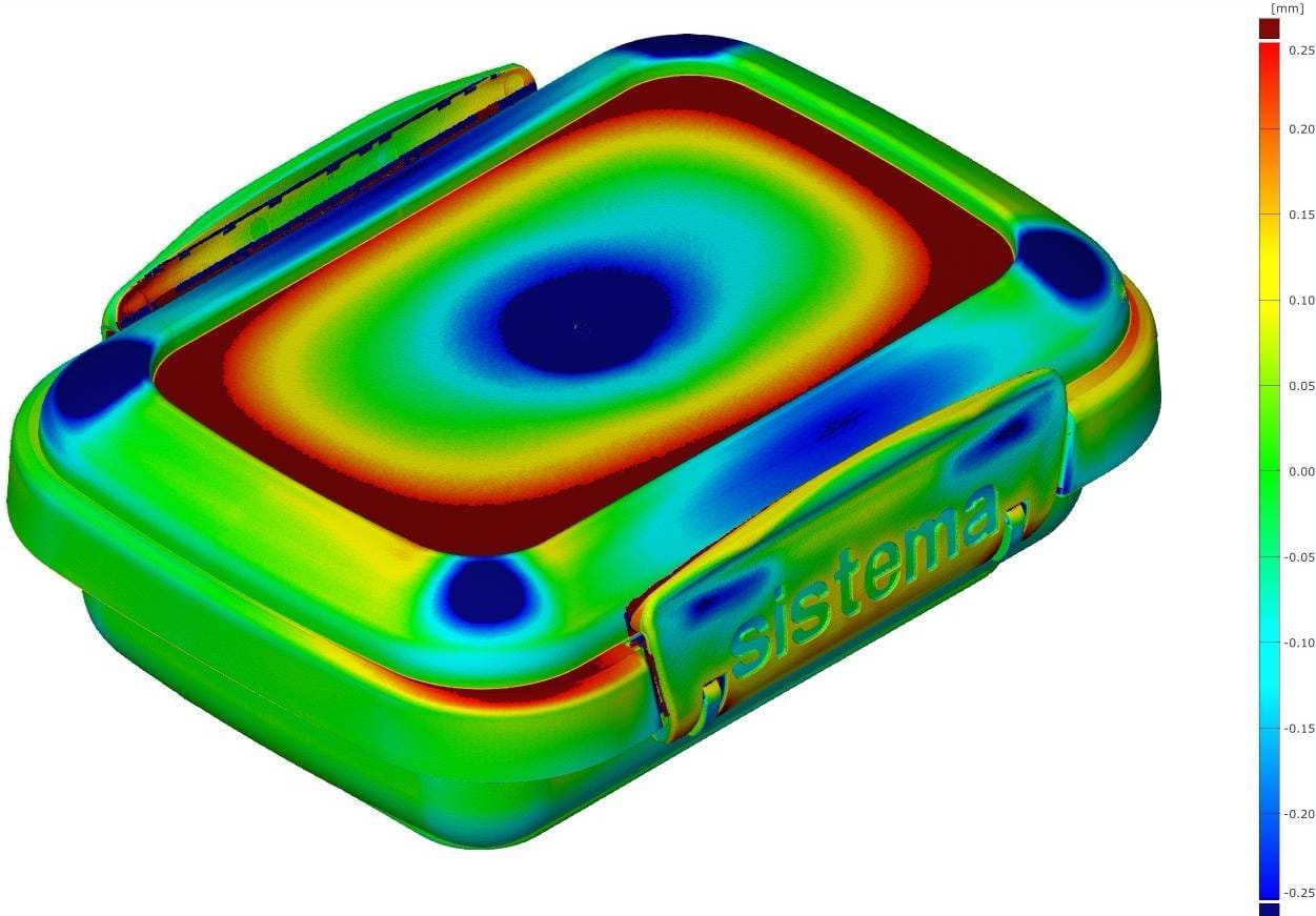
STEP 5: Validation
Once the CAD model is created, it is compared to the original scan to ensure accuracy. This step validates the reverse-engineered model against the physical object.
A color plot visualizing the difference between the two allows very quick and visual identification of possible discrepancies. Adjustments are then still possible to eliminate discrepancies.
The result is a validated CAD model that faithfully represents the original object.
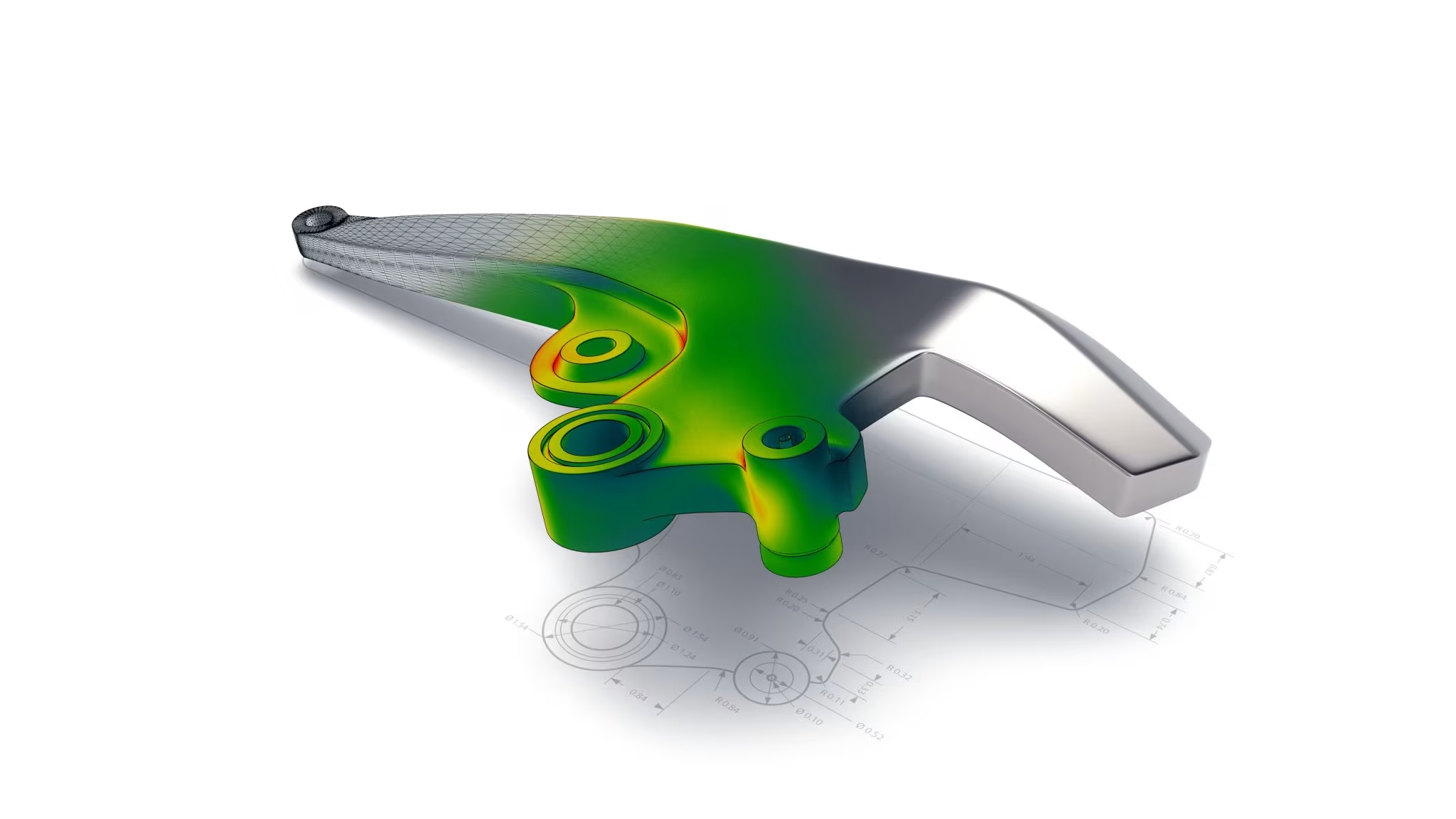
STEP 6: Analysis & Redesign
If the purpose of reverse engineering is to improve the design or functionality of the object, this step includes using the CAD model for further analysis and redesign. This step is performed again by our client where, for example, consideration can be given to:
- Simulations or stress analyses to understand performance.
- The design can be customized for better functionality, ergonomics, durability or efficiency.
The result is an optimized design that is ready for prototyping or production. Of course, this new design can again undergo a scanning process to check the dimensions and quality before moving to series production.
STEP 7: Prototyping or Production
The final CAD model is now ready to be used for production. Depending on the application, the file can be used for manufacturing methods such as CNC machining, 3D printing or injection molding.
An appropriate production method is selected, and results in a physical replica or improved version of the original object.
Lead time of a reverse engineering project
The lead time of a reverse engineering project depends primarily on two factors: the geometric complexity and the number of unique features of the part.
Simple prismatic parts, composed of planes, cylinders and standard shapes, are faster to model than organic or freeform surfaces. In addition, the number of features plays a role: a part with many different features requires more time, even when the individual features are not complex in themselves.
There is no fixed rule of thumb for lead time. Each project is assessed on a case-by-case basis. After an initial analysis of the part, we always provide a realistic estimate of the expected lead time.
Accuracy per material type
The accuracy of a reverse engineered CAD model is determined not only by the scanner, but also by the manufacturing quality of the physical part itself. The more precisely the part has been manufactured, the more accurate the digital reconstruction.
Typical accuracies per material type:
- Machined parts: ± 0.05 mm. Smooth, precisely manufactured surfaces can be reconstructed very accurately.
- Plastic parts (3D printing, injection molding): ± 0.25 mm. Rougher surfaces and possible deformations limit the achievable accuracy.
- Cast iron parts: ± 1–2 mm for the overall shape. Functional zones that have been post-machined (e.g. milled) offer higher precision.
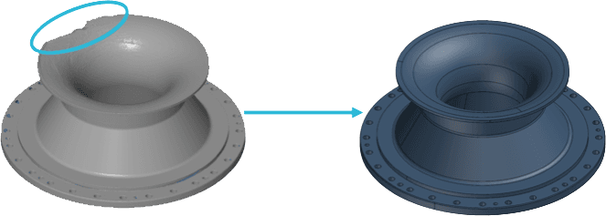
What if the part is damaged or incomplete?
Damaged or incomplete parts can also be reverse engineered. Cracks, wear or missing sections are reconstructed based on symmetry, references or surrounding geometry.
In addition, larger manufacturing defects or unwanted deformations can be filtered out during reconstruction. This is always done in consultation with the client, ensuring the end result matches the intended application exactly.
Can the model be used directly for production?
A reverse engineered CAD model provides a perfect starting point, but in many cases it is not immediately production-ready. There are three important reasons for this.
1. Each manufacturing technique requires different design rules CNC machining requires consideration of milling radii, clamping and tool access. Injection molding involves draft angles, wall thicknesses, ribs and shrinkage. And 3D printing demands minimum wall thickness, support strategy and orientation.
2. A scan-based model follows the object, not DFM principles The CAD model is an accurate reconstruction of the physical part, but does not automatically account for Design for Manufacturing (DFM) guidelines.
3. DFM is a separate engineering discipline Tolerance analysis, material selection, process settings and quality strategy fall outside the scope of reverse engineering. Therefore, a second expert is often needed to make the model production-ready.
We deliver the high-quality CAD model that serves as the starting point. From there, a production engineer can further optimize the design for the chosen manufacturing technique.
Our cases
- Reverse Engineering ,
- Xray CT scanning
- Optical 3D scanning ,
- Reverse Engineering ,
- Xray CT scanning
- Optical 3D scanning ,
- Reverse Engineering
Want to know more about Tetravision?
Please contact us here. We always respond within 24 hours.
Our experts are at your service

Sofie Rasschaert
Technical Account Manager

Jurgen Van Donink
3D Metrology Expert & CEO

François Justin
3D Metrology Expert & CTO
Frequently asked questions about
Reverse Engineering
What is reverse engineering with 3D scanning?
Reverse engineering is the process where we first digitize a physical object using 3D scanning or X-ray CT scanning and then convert it into an editable CAD model. The result is a STEP, IGES, or Parasolid file that you can use directly in your CAD software such as SolidWorks, Siemens NX, or CATIA.
How does the reverse engineering process work at TetraVision?
Our process consists of a fixed, systematic workflow. We start with calibration and verification of the scanner, followed by 3D scanning of the object (optical or via CT). Then we clean up the scan data and convert the mesh to a CAD model using specialized reverse engineering software such as Geomagic Design X and QuickSurface. Finally, we validate the result with a color plot that visualizes the deviations between the CAD model and the original scan. This way, you always receive a high-quality and validated end result.
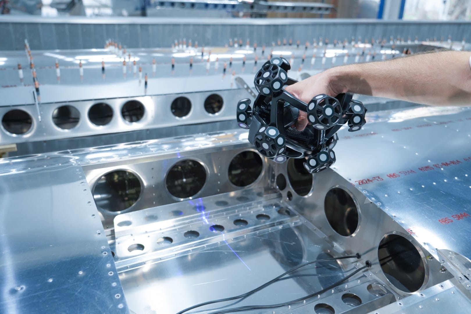
Which scanning technique is used for reverse engineering?
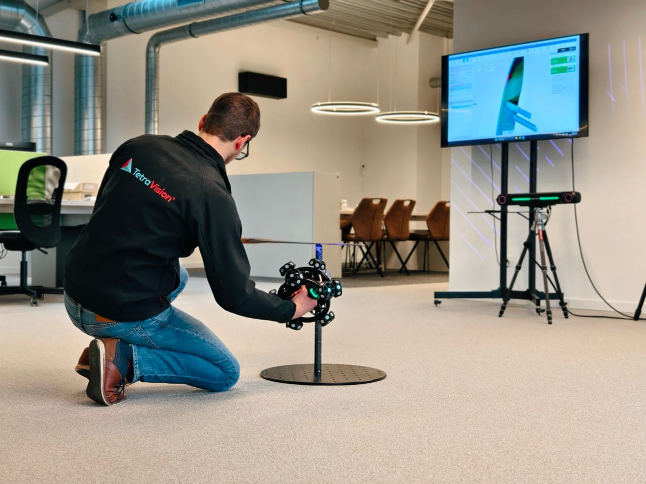
Depending on the part, we use our optical 3D scanners based on structured or laser light, optionally combined with photogrammetry, or one of our X-ray CT scanners. CT scanning is particularly suitable for parts with complex internal geometries that are not optically accessible. For larger objects that cannot be moved, we have various mobile scanners, ranging from small handheld to large tracking systems.
What file format will I receive after reverse engineering?
You will receive a CAD file in the format of your choice: STEP, IGES, or Parasolid (X_T / X_B). These are universal formats that can be opened in virtually any CAD software. Additionally, you will also receive the original scan data (STL) and a validation report that visualizes the deviations between the CAD model and the scan.
What is the difference between a 3D scan (STL) and a CAD model?
A 3D scan produces an STL file: a mesh of triangles that describes the shape of the object. This is very accurate but not editable in traditional CAD software. In reverse engineering, we convert this mesh into a true CAD model with editable features such as planes, cylinders, NURBS surfaces, and boolean operations. This allows you to modify the design, run simulations, or use it for production.
How is the CAD model validated?
After creating the CAD model, we compare it with the original scan. A color plot visualizes the deviations between both, so you can see at a glance where any differences are located. Adjustments are still possible at this stage to eliminate discrepancies. We work as much as possible according to general design principles such as perpendicularity and concentricity.
What applications is reverse engineering used for?
Common applications include restoring missing CAD data from existing parts, redesigning or improving products, preparing parts for production via CNC machining, 3D printing, or injection molding, and digitizing legacy parts for which no original design is available anymore.
Can you also reverse engineer complex freeform shapes?
Yes. When standard prismatic shapes (planes, cylinders) are not sufficient, we use NURBS surfaces (freeform surfaces) or a combination of both. Think of organic shapes, design parts, or complex mold surfaces. With software like Geomagic Design X and QuickSurface, we bridge the gap between 3D scanning and traditional CAD software.
How accurate is the reverse engineered CAD model?
The accuracy depends on two factors: the accuracy of the underlying scan on one hand, and the manufacturing quality of the part itself on the other. Typical accuracies per material type: machined parts ± 0.05 mm, plastic parts (3D printing, injection molding) ± 0.25 mm, and cast iron parts ± 1–2 mm for the overall shape (post-machined functional zones offer higher precision).
In reverse engineering, we model the part according to the intended geometry. A sink mark or dent on a surface, for example, is modeled away to a perfect flat surface, which deliberately results in a deviation from the scan. These choices are always transparently documented in the validation report, where we visualize the differences between scan and CAD model. With our ISO 17025 accredited measurement equipment, we achieve scan accuracies down to 0.005 mm.
How quickly can a reverse engineering project be delivered?
The lead time depends on the geometric complexity and the number of unique features of the part. Simple prismatic parts are faster to model than complex freeform surfaces. But the number of features also plays a role: many different features extend the timeline, even if they are not individually complex. Each project is assessed on a case-by-case basis. Contact us for a concrete estimate, we always respond within 24 hours.
What does reverse engineering cost?
The price depends on the complexity of the part, the type of surfaces (prismatic vs. freeform), the desired accuracy, and the output format. We create a customized quote for each project. Request your quote here, you will receive it within 24 hours.