CT scanning and reverse engineering of a replacement part for Machinified BV
When a part breaks and the original is no longer available, reverse engineering offers a solution. For Machinified BV in Leuven, we converted a cracked plastic swimming pool component into a complete CAD model. Using our ZEISS Metrotom 6 Scout and QuickSurface’s reverse engineering software, we reconstructed the entire geometry, including the threads, so that the part could be reproduced via 3D printing.
Project at a glance
| Customer | Machinified BV (Leuven, BE) |
| Application | Reverse engineering of a cracked plastic swimming pool component for reproduction |
| Component | Plastic cover component with fine internal threads |
| Challenge | Part has cracked and is no longer available; no original CAD data is available; the thread is critical for a proper fit in the existing pool installation |
| Scanning Technology | X-ray CT scanning (ZEISS Metrotom 6 Scout) |
| Reverse engineering | QuickSurface |
| Validation | ZEISS Inspect, with color plot scan vs. CAD |
| Output | Complete CAD model in STEP format, including a validation report in PDF |
| Reproduced by the customer | SLS 3D print in PA12 |
| Lead time | About two days |
The customer’s request
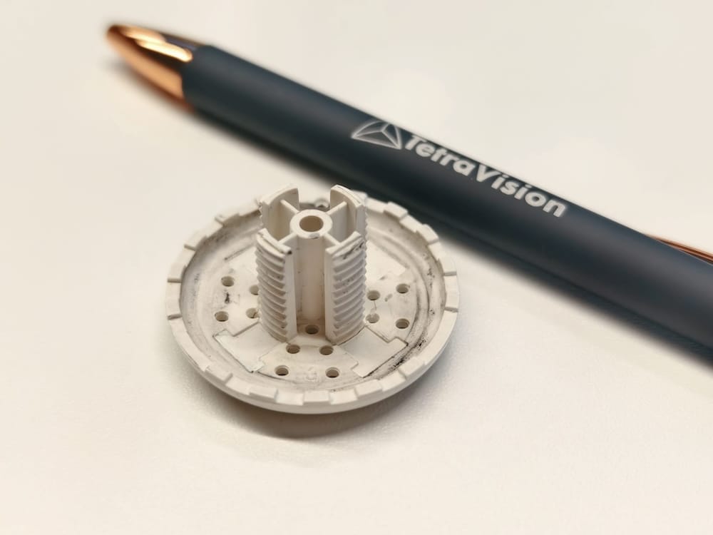
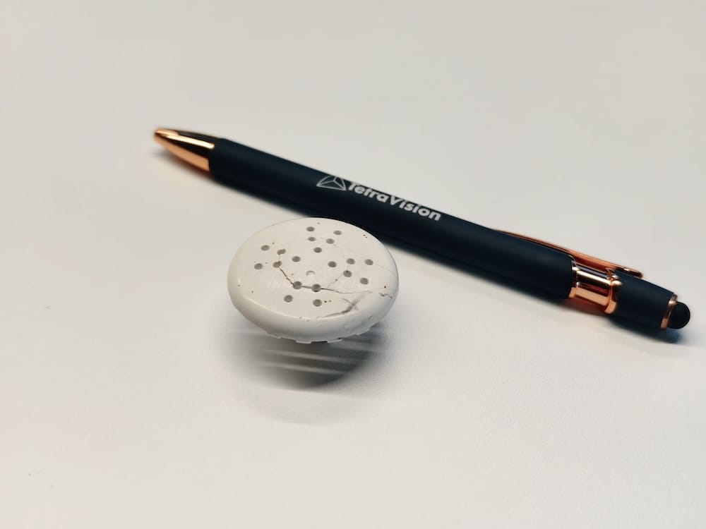
Machinified BV from Leuven approached us with a seemingly simple problem: a cracked plastic component from a swimming pool system for which no replacement was available. The part had to be remanufactured, which first required creating a precise CAD model of the existing component.
The challenge lies in the internal geometry: the component features a detailed thread that must fit exactly into the existing swimming pool setup. There is no margin for error with that thread. If the thread doesn’t fit, the entire part won’t fit, and the whole process will have been for nothing.
On top of that, the physical condition of the original was a concern. The part showed a clear crack, as well as localized wear and deformation. The CAD model therefore had to do more than simply copy the scan; it had to reconstruct the original geometry as the part was originally designed, without incorporating the damage.
Our approach
For this project, we opted for a combination of X-ray CT scanning and reverse engineering using QuickSurface. CT scanning was the obvious choice here: the part features internal geometry and a thread that are either impossible or much more difficult to capture accurately using optical 3D scanning. With CT scanning, we obtain 100% of the data, both internal and external, in a single run and without causing any damage.
Step 1: X-ray CT scanning with the ZEISS Metrotom 6 Scout
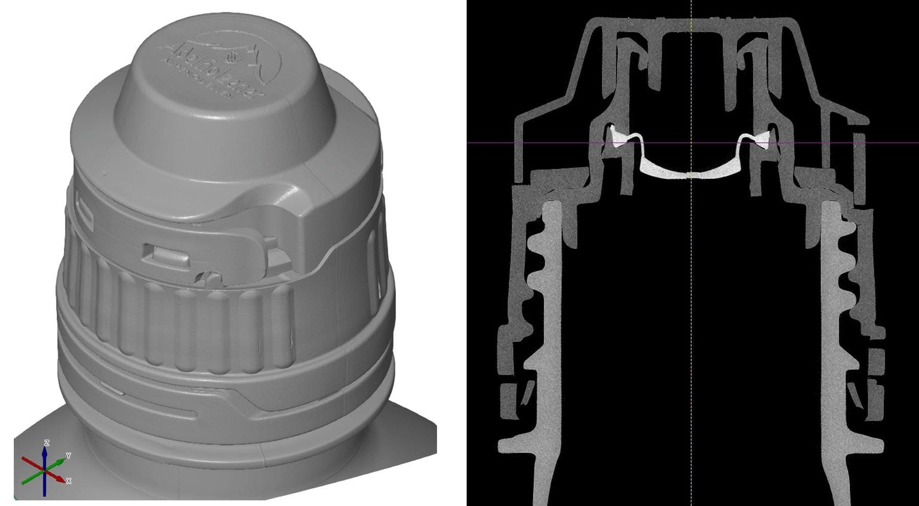
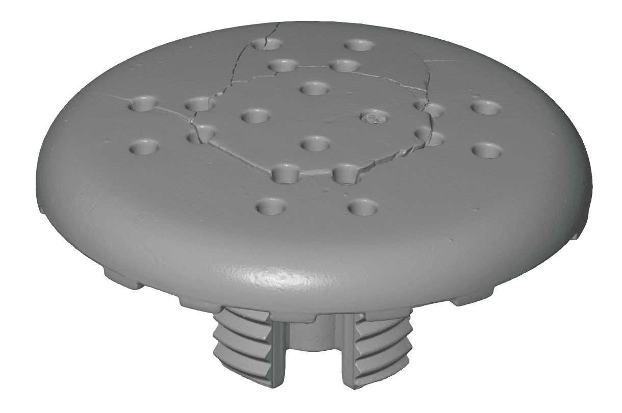
The ZEISS Metrotom 6 Scout is ideally suited for plastic components such as this one. By combining a 3k detector with a 225 kV X-ray source, we achieved the resolution and contrast needed to capture all details, including the fine screw threads, with sharp clarity. The result is a high-resolution mesh that accurately represents the part’s entire internal and external geometry.
The advantage of CT scanning is that it visualizes areas that are difficult or impossible to access with traditional measuring equipment. For this component, that was not a luxury but a necessity: without the internal data, a correct thread reconstruction simply would not have been possible.

Step 2: Reverse engineering with QuickSurface
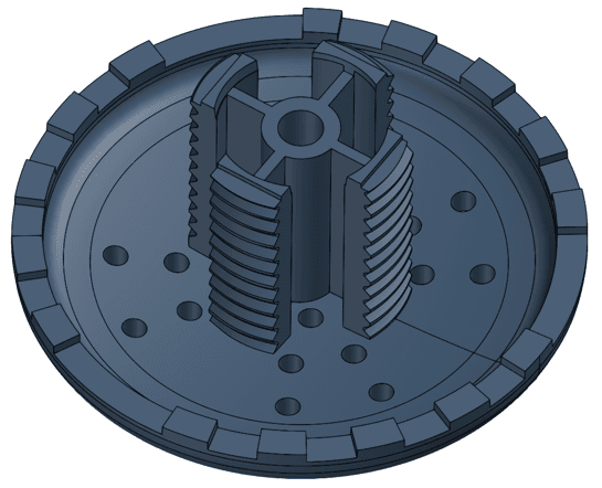
Using the scan data as a starting point, we then got to work in QuickSurface. This software was the logical choice for this project: it allows us to quickly build a clean, production-ready solid body from a mesh, with specific functionality for revolved geometry and thread reconstruction.
QuickSurface itself detailed the entire workflow for this project in a comprehensive video, using our scan data as the starting point. The video shows, step by step, how to go from a scanned, cracked plastic component to a fully reusable CAD model. For anyone considering a similar process, this is one of the most comprehensive online demonstrations of an end-to-end scan-to-CAD workflow on a real part.
The workflow reflects the typical steps of a reverse engineering process in QuickSurface:
- alignment of the scan data and definition of a reference system,
- creation of the revolved base geometry of the component,
- reconstruction of the thread using a fitted helix and sweep,
- reworking of recesses using sketches, patterns, and Boolean operations,
- delivery of a clean, production-ready CAD model.
This type of workflow is ideal for replacement parts, older components, and repairs for which the original CAD data is no longer available.
Step 3: Validation in ZEISS Inspect
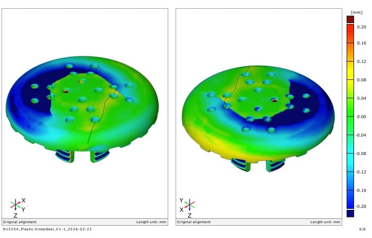
No reverse engineering project is complete without validation. At the end of the process, we compared the reconstructed CAD model in ZEISS Inspect with the original scan data. A color plot shows at a glance where the CAD model exactly matches the measured geometry and where there are intentional deviations.
The validation shows that the vast majority of the surface lies within approximately ±0.08 mm of the scan geometry, with green and cyan as the dominant colors. The largest deviations are logically located at the cracked edges and in areas of local deformation of the worn original. That is exactly what a good validation report should show: not only that the CAD model matches the scan, but also where deliberate choices were made to, for example, smooth out the crack or wear in order to create a reproducible part.
In this way, the customer not only knows that the model is correct, but also why certain regions deliberately deviate from the original. That is the difference between a rough scan-to-CAD conversion and a validated reverse engineering process.

The result
Machinified now has a complete and validated CAD model of the pool component in STEP format. Based on this model, the company had the new part manufactured in-house using SLS 3D printing with PA12. As a result, a part that was no longer available anywhere is now available again, with a fit that accurately replicates the internal thread.
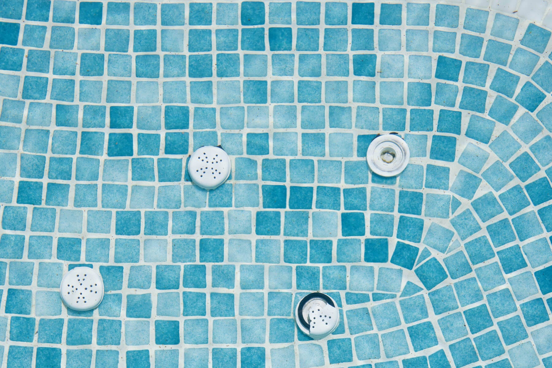
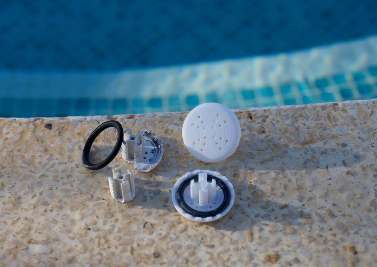
This makes the project a great example of where reverse engineering stands today: from a physical, cracked, and no-longer-available part to a new one that can be printed within a few days.
Why CT scanning made the difference here
For reverse engineering projects involving plastic parts with internal features or fine thread geometries, X-ray CT scanning is often the only technique that provides the full picture. Optical 3D scanners based on structured or laser light are extremely fast and offer high resolution, but they can barely penetrate the interior of a hollow or complex-shaped component.
CT scanning captures the complete internal and external geometry in a single run, non-destructively and with the level of detail required to correctly reconstruct a thread, for example. An additional advantage is that multiple (smaller) parts can be scanned simultaneously, making CT scanning cost- and time-efficient even for larger production runs.
For customers like Machinified, who want to reproduce a part for which no CAD data remains, this is the difference between “roughly” and “exactly fitting.”
A similar project?
Do you have a part that is worn out, cracked, or no longer available, and would you like to have it remanufactured? We’d be happy to assist you using a combination of scanning and reverse engineering. Be sure to read our previous case study, A lost part digitally restored, which details a similar project where we combined optical 3D scanning and CT scanning to digitize a unique race car part.
Contact us at info@tetravision.be or +32 16 91 04 20. We always respond within 24 hours.