Custom builds, designed around real-world geometry
When you build a racing buggy from scratch around a 1300cc Hayabusa engine, your design literally runs into hardware limitations. The exhaust system, drivetrain, and engine mounts all have to fit around an engine block for which you have no CAD data. Suzuki doesn’t provide that information, and a caliper won’t get you anywhere.
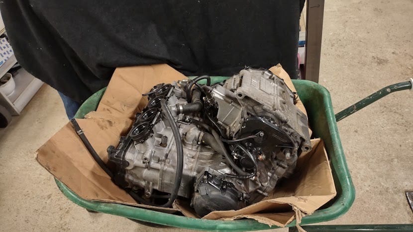
Efi Veys (Veyzer BV) and Cedric Van Molle, two techies who spend their free time building their own FX buggy, reached out to us. They had one request: create a 3D scan of the separate engine block so we could design around it in Catia.
Who is behind this project?
Cedric Van Molle is a full-time technical draftsman who works with Inventor and Catia V6 on a daily basis. In his spare time, he and Efi Veys of Veyzer BV are building a handmade cross-buggy to race. The frame is constructed from hand-bent and hollowed-out Cromoly tubes, and the Hayabusa engine is being fitted with a turbocharger to turn it into a true powerhouse.
The project has been underway for some time and is being put together outside of working hours, with attention to every detail. It’s exactly the kind of project where a solid foundation at the start saves all the design iterations down the line.
The challenge: designing without CAD data
With a custom build based on an existing engine, the challenge isn’t the engine itself, but everything that needs to fit around it. In Catia, Cedric and Efi had to design the following, among other things:
- The exhaust line, which must run along the frame without coming into contact with it.
- The drivetrain, properly aligned with the engine shaft.
- The engine mounts, which securely anchor the engine to the frame.
For each of these components, you need the exact external dimensions of the engine block, including all cooling fins, housings, and mounting surfaces. A simplified model is not sufficient, because even the slightest deviation will mean having to go back to the drawing board later on.
A 3D scan was the logical place to start. The only question was: how do we create one that integrates seamlessly into Catia?
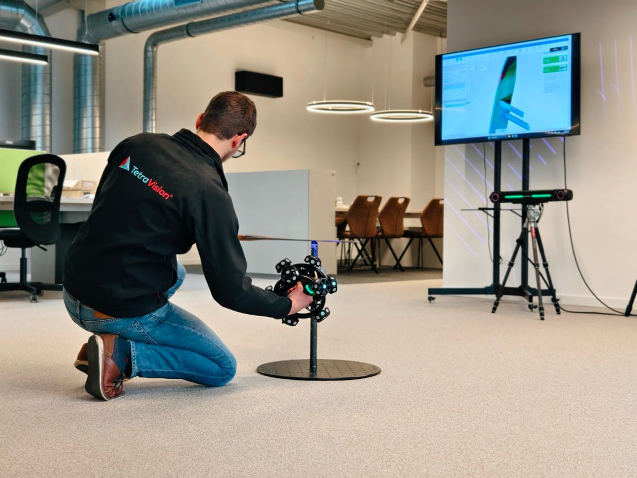
Our approach: scanning while you wait
Cedric and Efi dropped by with the engine block. For projects like this, where the item is valuable or the owner doesn’t want to let it out of their sight, we organize the scan so that the customer can take the item back the same day. We scan it on-site, the customer waits in our office with a cup of coffee and Wi-Fi so they can keep working in the meantime, and the engine block leaves our building in the same condition as when it arrived.
The entire scanning session took about two hours. After that, we processed the data, and by the time Cedric and Efi got home, the download link was ready.
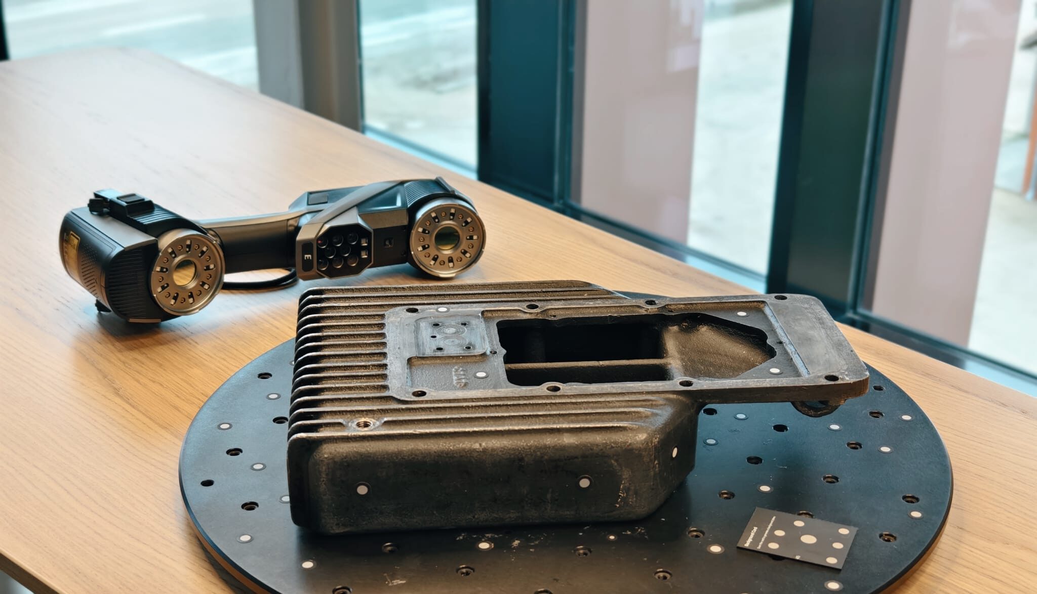
Technology: ATOS III Triple Scan with evaporating scanning spray
For this project, we used our ZEISS ATOS III Triple Scan, a mobile structured-light 3D scanner that captures maximum detail on complex geometries such as cooling fins, threads, and internal connections. An engine block has many reflective and metallic surfaces, which poses a challenge for optical scanners. We therefore used AESUB evaporating scanning spray to temporarily neutralize the reflection. The spray evaporates on its own within a few hours, so we return the engine block without any residue or post-processing.
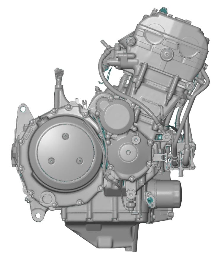
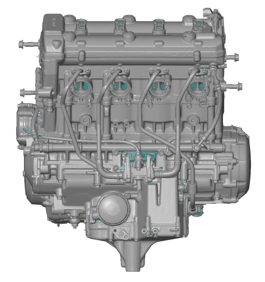
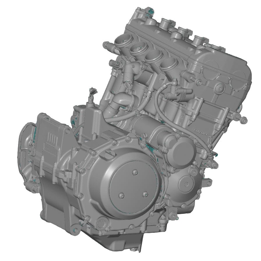
The result: a digital twin with an accuracy of ±0.05 mm
What Cedric and Efi received from us was a complete digital twin of the engine block. The key figures:
- Object dimensions: 500 x 500 x 600 mm
- Accuracy: +/- 0.05 mm across the entire block
- Two STL files provided: the original scan (approx. 350 MB) and a filtered version (approx. 150 MB)
- Fully aligned in a logical coordinate system, allowing for direct import into Catia
That last point deserves special mention. Importing a raw STL file into CAD is not a viable starting point. We ensure that the scan is properly aligned to a logical coordinate system, so that the customer can start designing right away without first having to spend an hour on repositioning and alignment.
Providing two STL versions is standard practice for us. The original scan contains all the captured detail, but a 350 MB file can be slow to load in some CAD environments. The filtered 150 MB version offers smoother performance without losing any relevant detail. If the client is working on a high-end system, they’ll use the original scan; otherwise, they’ll opt for the lighter version. If necessary, we can filter the data further upon request.
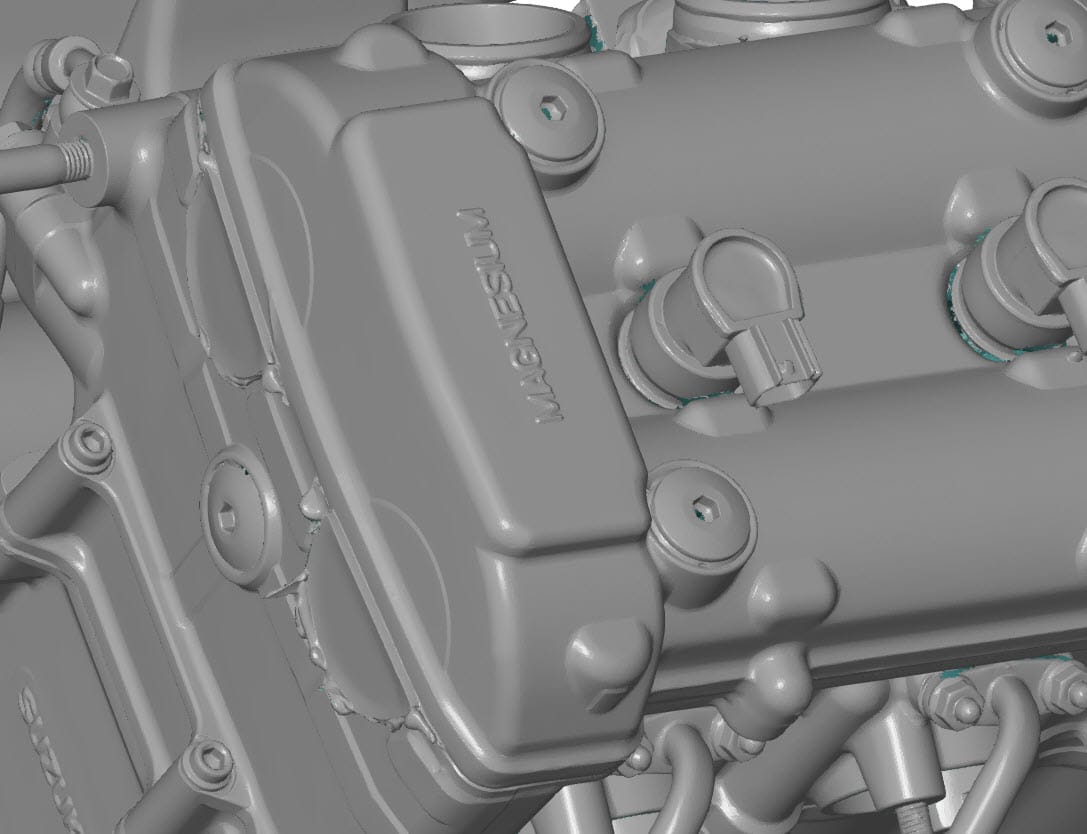
A detail that speaks for itself
The detailed images below immediately show why a high-quality optical scan makes all the difference here. Every cooling fin, thread, and mating surface is captured in its entirety. Nothing has been smoothed out or interpolated.
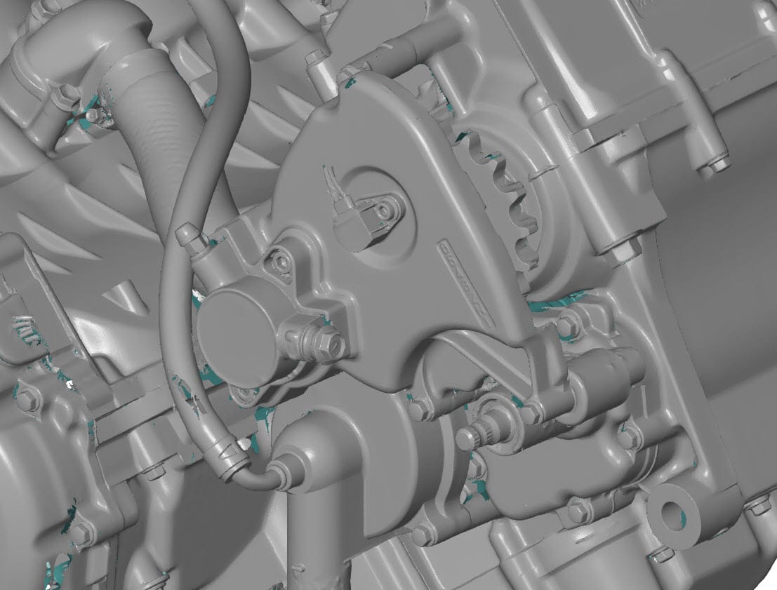
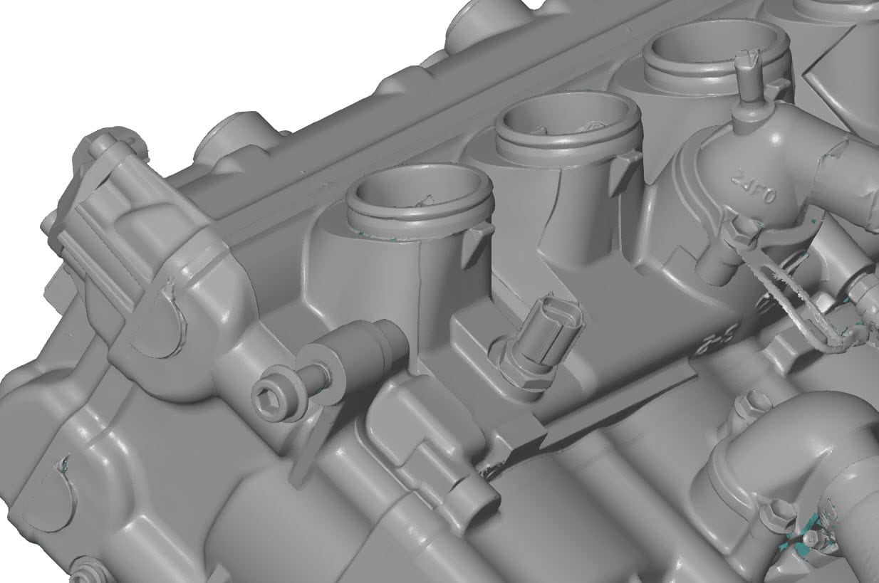
Cedric later confirmed that the STL file allowed him to immediately start modeling around the engine block in Catia. Catia, along with Siemens NX, is one of the few professional CAD packages that handle STL data very well. In other CAD environments, an intermediate step is often required (fitting geometric features and exporting to IGES or STEP), but in this case, the STL was sufficient.
Today, we would handle this differently
Since this project, we have expanded our product range to include the Scanology NimbleTrack-E Gen2, a wireless laser tracking system. If we were to scan this engine block again today, that would be our choice.
The result in terms of accuracy would be comparable, approximately +/- 0.05 mm, but the process would be significantly faster in two respects:
- No more scanning spray required. The NimbleTrack-E Gen2 captures reflections without any surface pre-treatment. This saves preparation time, and the customer gets their object back exactly as they brought it in.
- Faster scanning sessions. Wireless laser tracking technology allows us to capture large surfaces more quickly while maintaining detail. A two-hour session would be reduced to a fraction of that time.
For clients working on a similar project, this means in practice: even less time on-site, and a functional digital twin on your hard drive even faster.
Who might find this approach useful?
The Hayabusa project is not an isolated case. Whenever you want to create a new design based on an existing physical object for which no usable CAD data is available, high-precision 3D scanning is the logical starting point. Specific examples:
- Custom builds in motorsports, the automotive industry, and the motorcycle sector, where you need to design around existing engines, frames, or bodywork.
- Restoration and restomod projects where original drawings are missing.
- Retrofit engineering, where you want to integrate new parts into existing assemblies.
- Prototyping based on existing products or mock-ups.
- Product development for components for which the supplier does not share CAD data.
The common denominator: a single, accurate starting point saves you from all the iterations that arise later when your design doesn’t match reality.
Are you working on a custom build or restoration?
Give us a call or send us an email. We’d be happy to work with you to determine whether optical 3D scanning or X-ray CT scanning is the right starting point for your design process.