Is it possible to scan and then analyse parts in clamped state? Definitely!
Is there a better, faster and more cost-effective way to do this? Undoubtedly!
Introduction
Regularly we get the question whether it is possible to scan and then analyse parts in clamped position.
We rarely clamp a part in a (custom-made) fixture. This directly affects the scanning itself, and we can capture less data where the part is clamped. In addition, making a specific fixture can also be very time- consuming.
Fortunately, there is a solution for this! Namely, we can fully digitally clamp/de-warp a part. This allows us, for instance, to eliminate the influence of gravity, measure the parts as they would be in their assembled state (= most common), or straighten warped parts.
So with this post, we want to take a closer look at the functionality of virtual clamping in Zeiss Inspect, and how it offers a better alternative to physical fixtures.
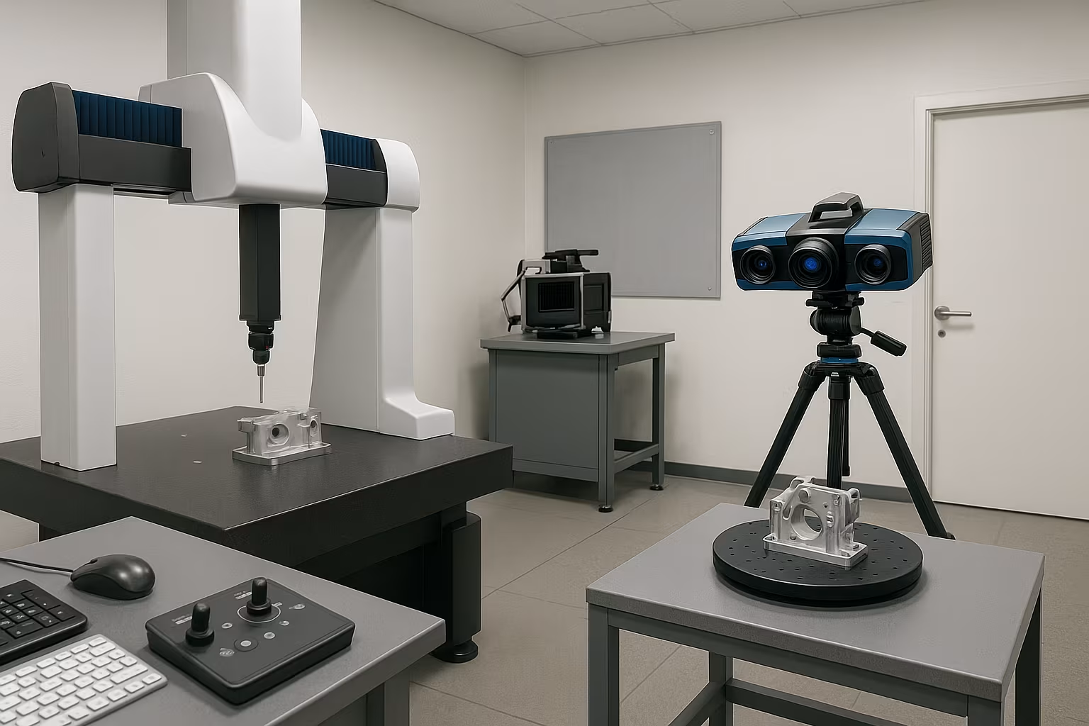
Disadvantages of a physical fixture
COST:
Using a physical fixture can be expensive. On the one hand, it is very time consuming to design, create and validate a correct fixture. On the other hand, a fixture often has to be used and stored in a controlled environment. On top of this, there is also the cost of materials, and the entire cycle has to be repeated with each product modification.
USAGE
When using a fixture, some problems/risks can occur. For example, repeatability is affected by the user and the order of clamping. Measuring the object in clamped state is also not always obvious, as the fixture limits the accessibility of some zones/areas of the part.
Zeiss de-warping tool
Zeiss has a de-warping tool that consists of 2 scripts. The first is ‘Voxelizer’ and the second is ‘Remove Warpage’. Before using this tool, a few things are important:
- We always need a CAD-model. (Or a non-deformed mesh.)
- The part should be made of a uniform material.
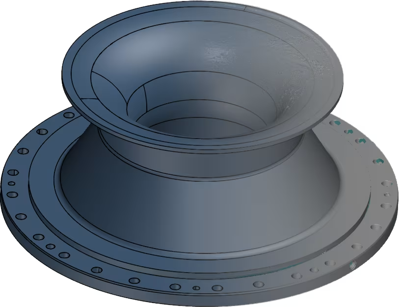
When we want to straighten an object, we need a CAD-file of the effective part.
If we want to virtually assemble a part, we also need this for the receiving part.
Materials with variable stiffness, depending on direction, cannot be virtually clamped. For example, consider materials with fibres in a certain direction to improve stiffness.
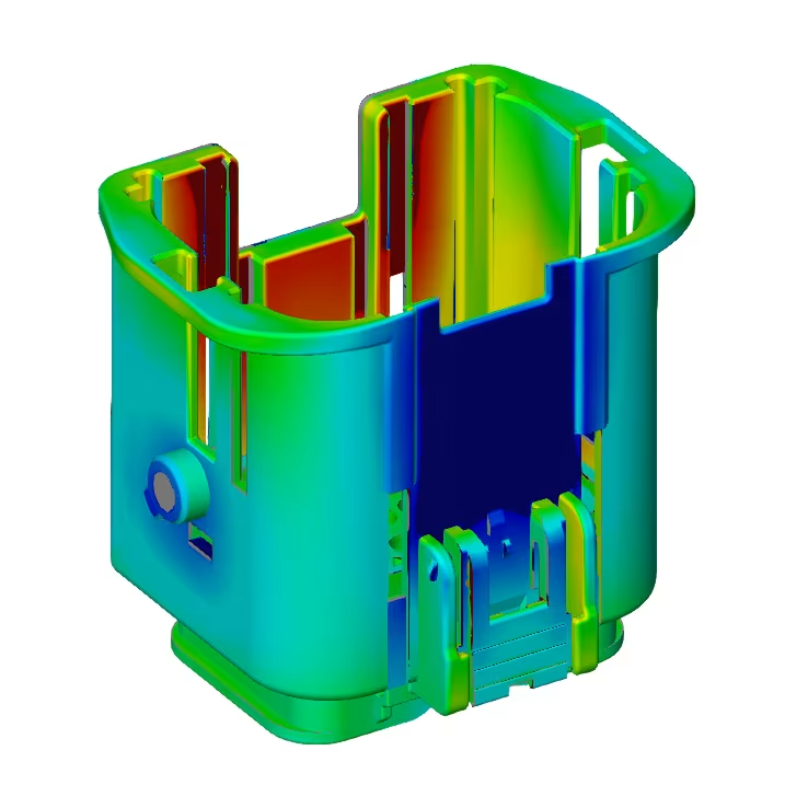
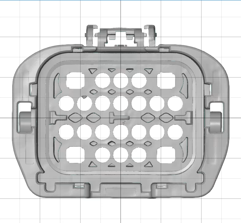
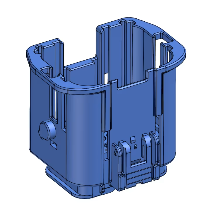
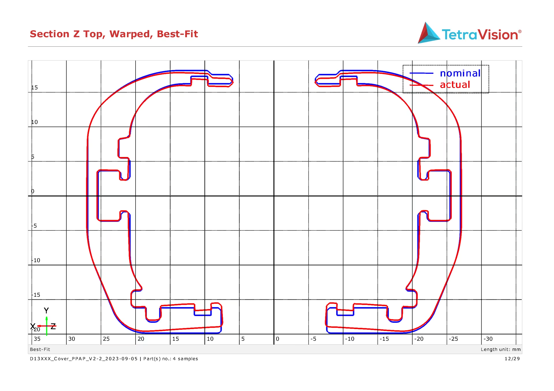
As an example along here, we use a part that has been kinked inwards on its 4 side faces, and straightened back with the de-warping tool.
Voxelizer
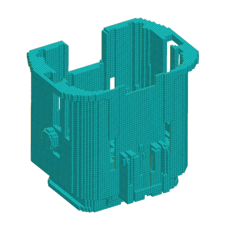
The Voxelizer is used to convert the CAD file to voxels (cubes). When converting to voxels, we need to include some parameters, most of which are related to the material:
- Voxel size
- Density
- Young’s modulus
- Poisson’s ratio
Along here you can see the result. This is what we call the deformation model, a Finite Element Method (FEM) volume that contains all the relevant structural mechanical properties of the part. This model is the basis for performing a de-warping.
Remove warpage
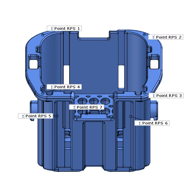
Reference points:
The part must first be fixed in its 6 degrees of freedom (DOF). We do this based on 6 (or more) reference points. Actually, here we make an alignment of the object based on these points. During de-warping, the object will not deform at these points.
For our case, we use 7 points:
- Point 1-4: Defines Z-plane
,Normally we would define this plane with 3 points but in this case the result became better when using 4 points. This way, we can fix the 4 corners of the object and they will not deform undesirably.
- Point 5 -6: Defines Y-plane
- Point 7: Defines X-plane
Clamping points:
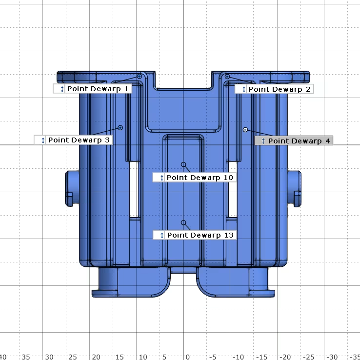
Next, we need to critically examine our object and determine exactly where we want to clamp/straighten it. For this we usually use the mounting points of the object. Meaning; we will virtually “mount” the deformed object on the receiving part. This allows us to verify:
- Whether the assembly is possible at all.
- Whether the dimensions are still within tolerance after assembly.
- Whether there is no unwanted distortion in other locations.
Should the part not be adequately clamped in the assembled state, we can still iterate to add additional clamping points. This allows us to determine where additional mounting points are needed to fit the part into its desired shape.
This is a major advantage of virtual clamping over physical fixturing. Namely, we can add additional clamping points quickly and virtually free of charge, whereas with a physical fixture this becomes time-consuming and costly.
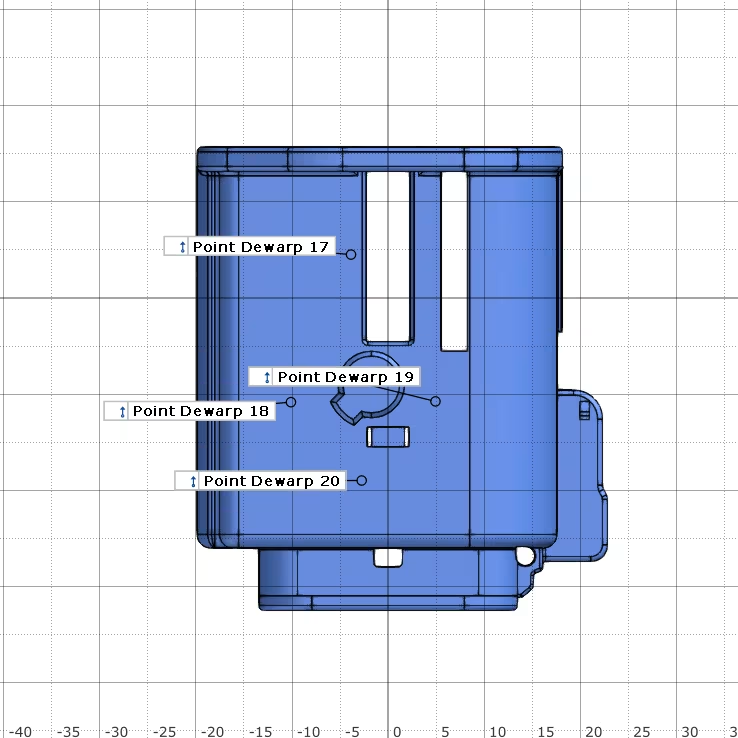
In our case, the 4 side planes must be drawn outward, since they are bent inward. So we indicate some points on these planes. Above you can already see many points iteratively added (you can see that by the numbering). We will always try to get a result with as few clamping points as possible. If not, we will add some points where we see that the clamping does not yet have the desired effect.
We pass these points into the de-warping tool as clamping points. At these points, the tool will thus try, in several iterations (max. 10), to bring the point lying on the mesh as close as possible to the current point on the CAD. In the process, the tool will also deform the environment around the point according to its material properties that we have previously given it.
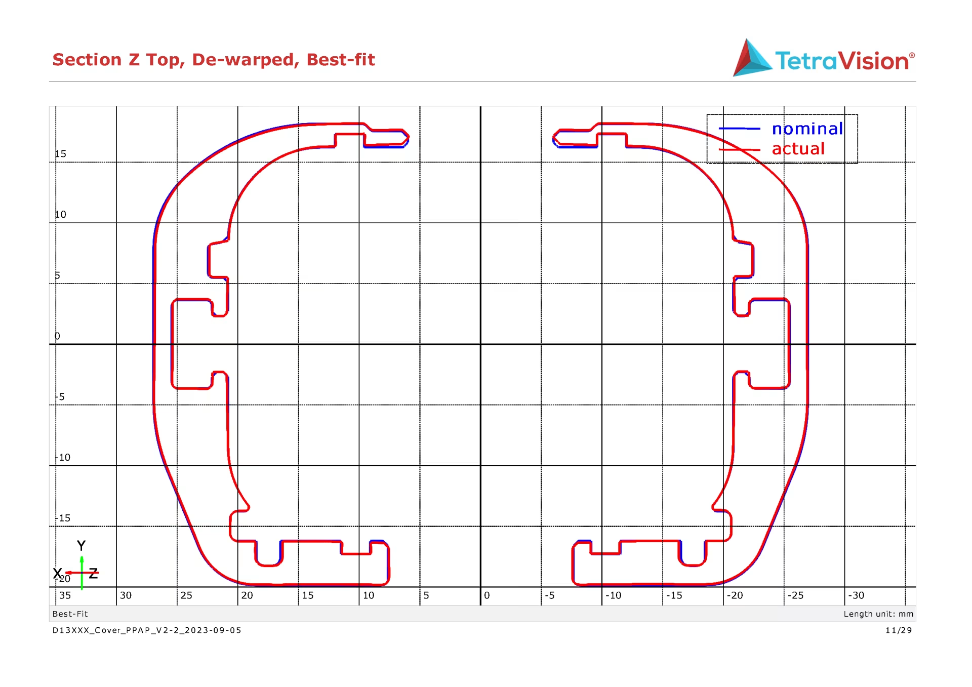
Results

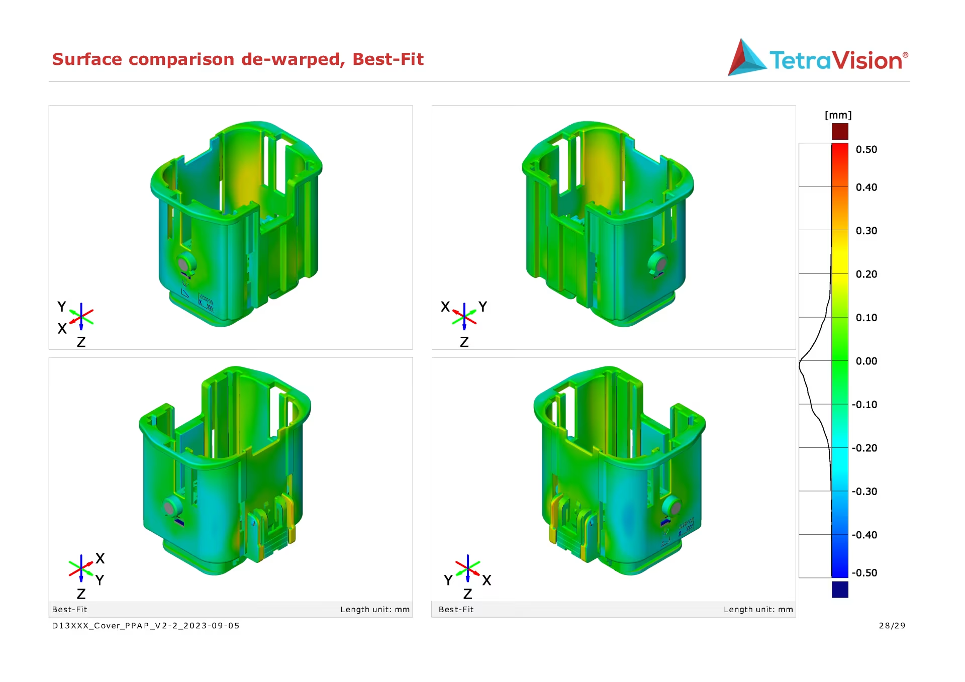
Conclusion
When we virtually clamp an object, we are not inconvenienced from all the possible disadvantages of a physical fixture.
- We do not need an individual fixture per part to be stored.
- We need to perform only 1 measurement instead of several (clamped and unclamped).
- We can quickly and efficiently add or omit clamping points, promoting the iterative process.
- The repeatability is very good because it is not affected by the user.
- We can still measure the entire object in clamped state.