Scanning in combination with Reverse Engineering
To reproduce this part, we made an optical 3D scan and used it as a reference for reverse engineering a new CAD model.
We used an ‘auto-surface’ modelling approach.
Process: step by step
Process
- NO spray needed
- Scanning in “free state,” with some reference points on the rod.
- Digitizing the whole thing + converting to CAD
Technology
- GOM Atos III Triple scan with 320MV (measuring volume)
- Automatic rotation table
- Geomagic Design X
Post-processing
- Plugging holes + Auto-surfacing
- Scan filtering to reduce file size.
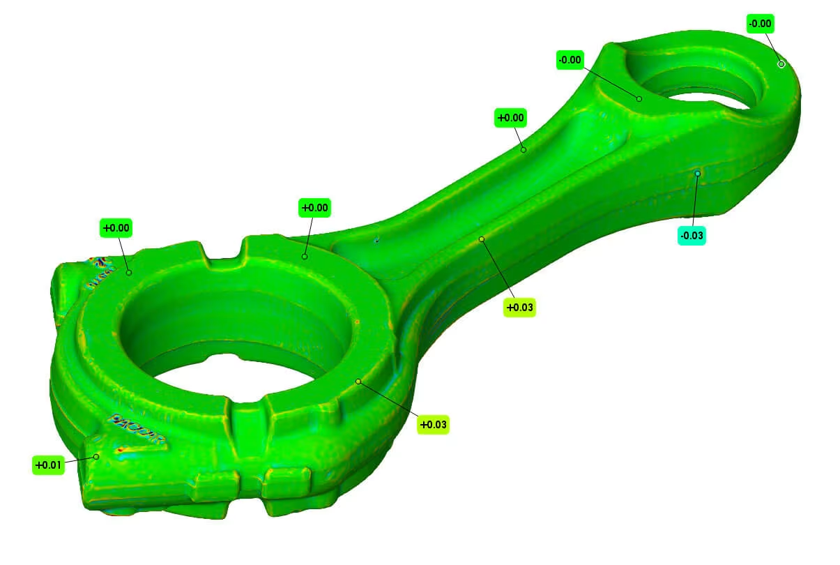
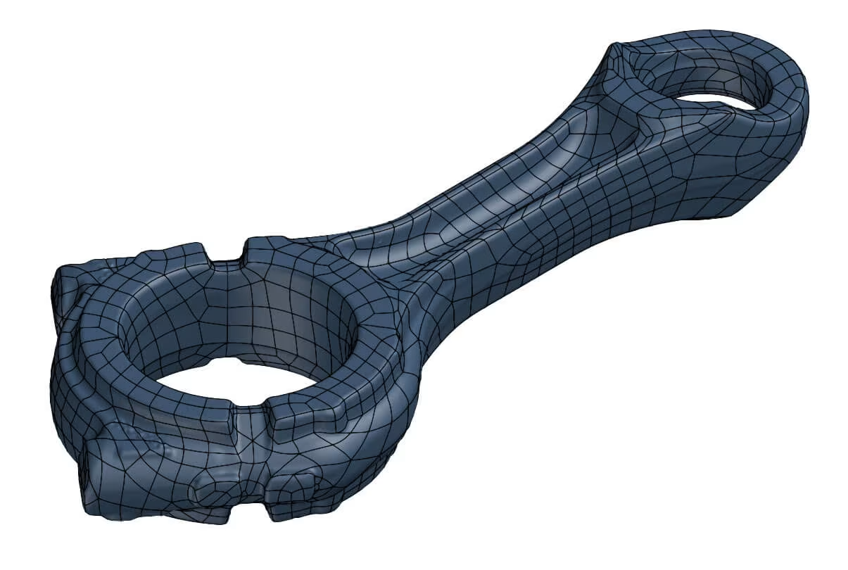
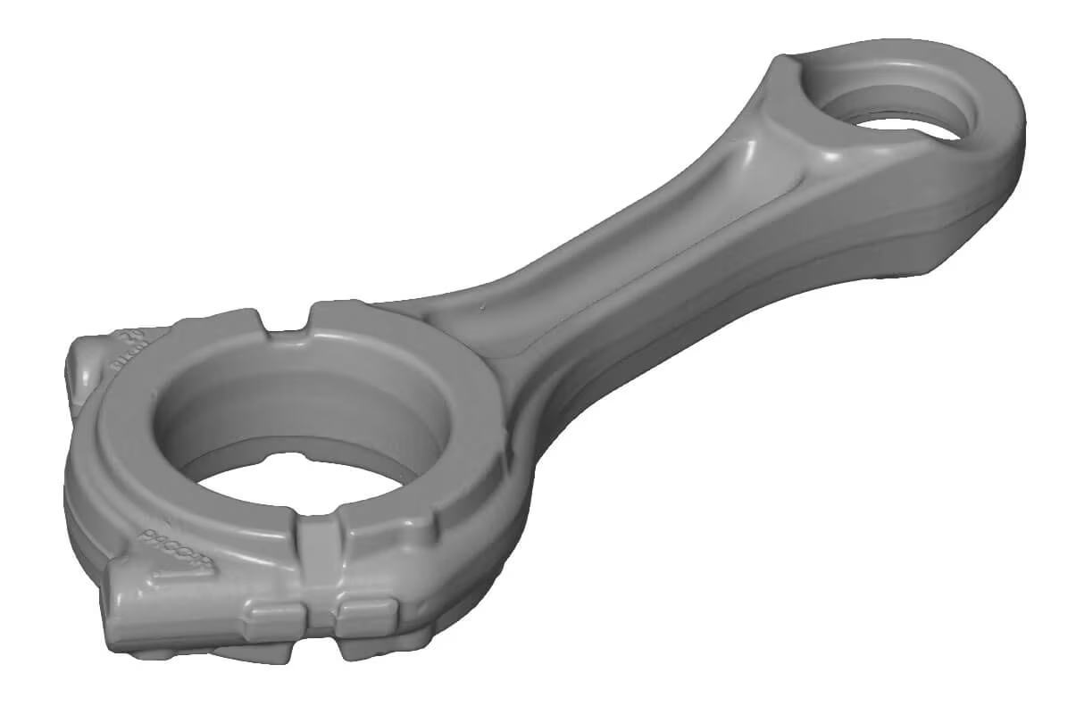
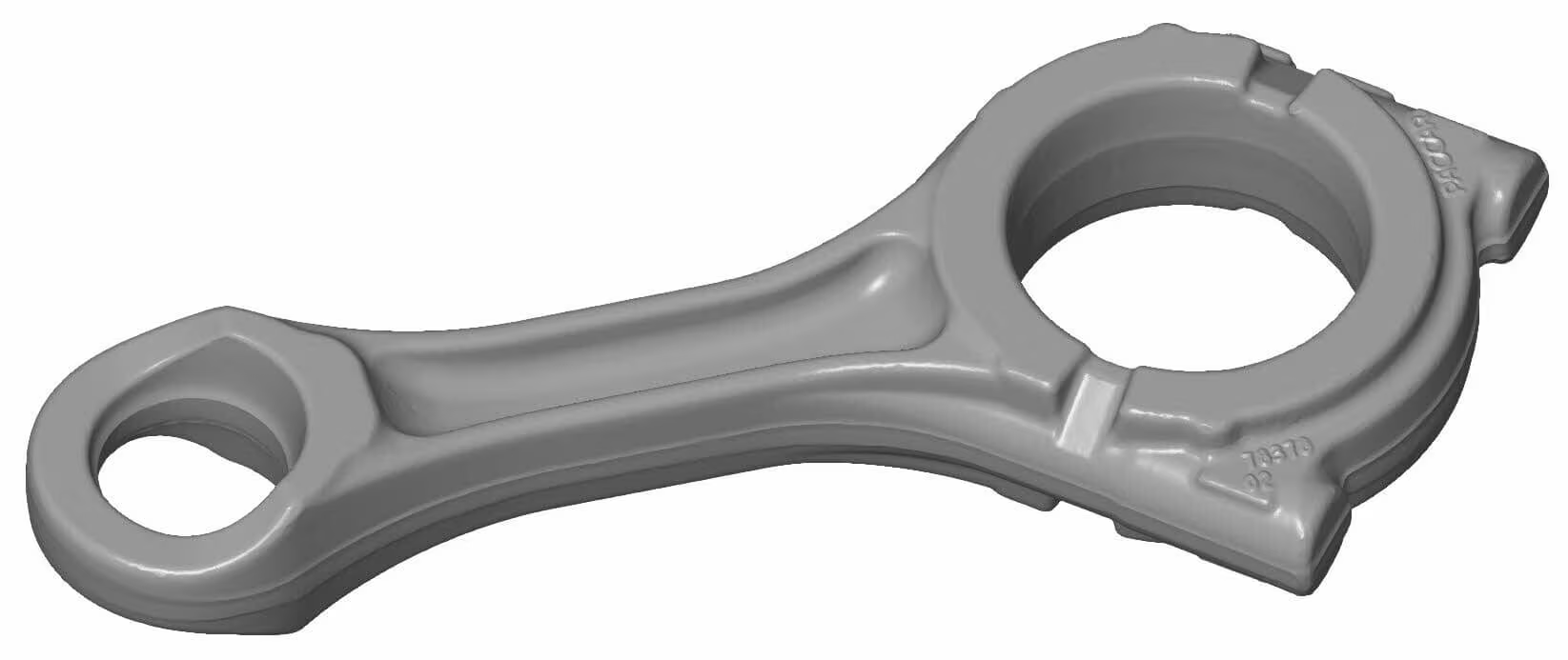
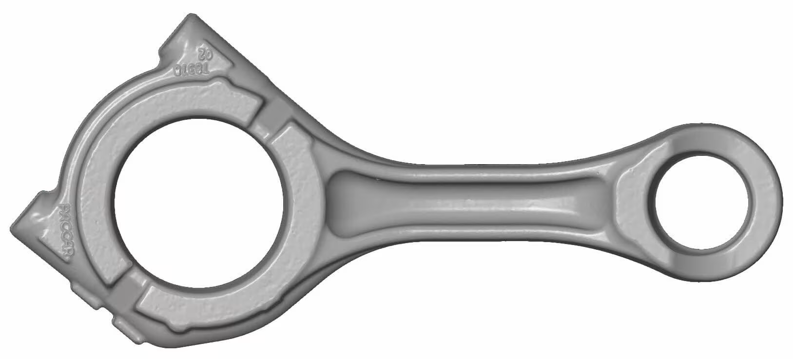
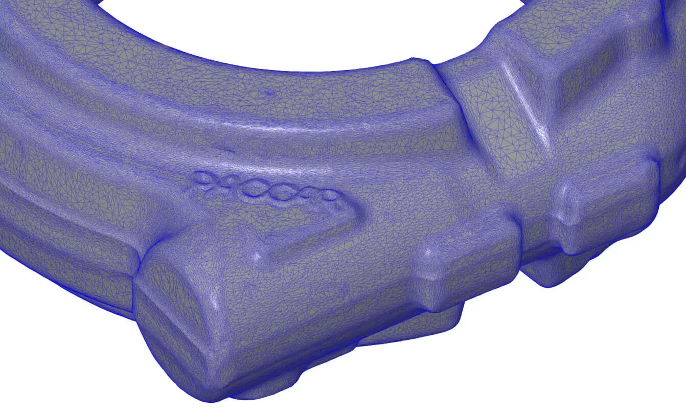
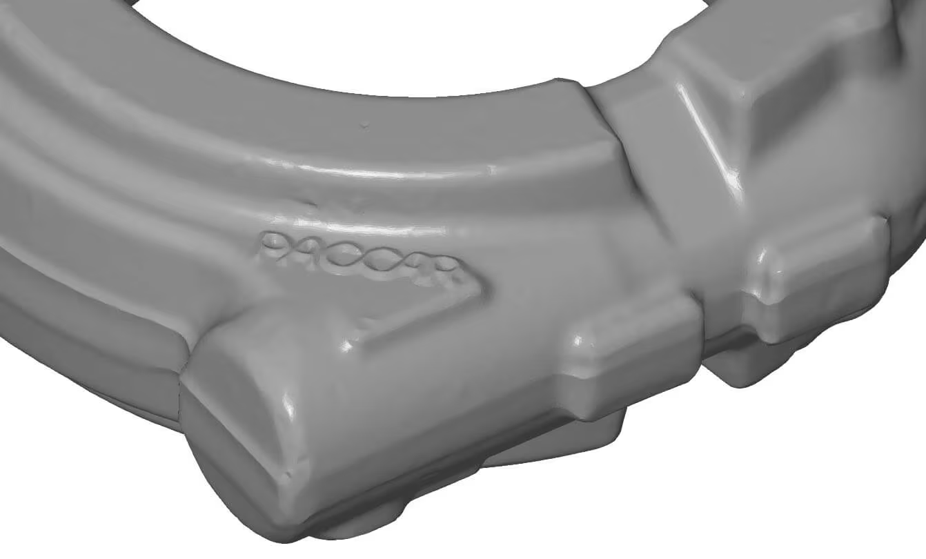
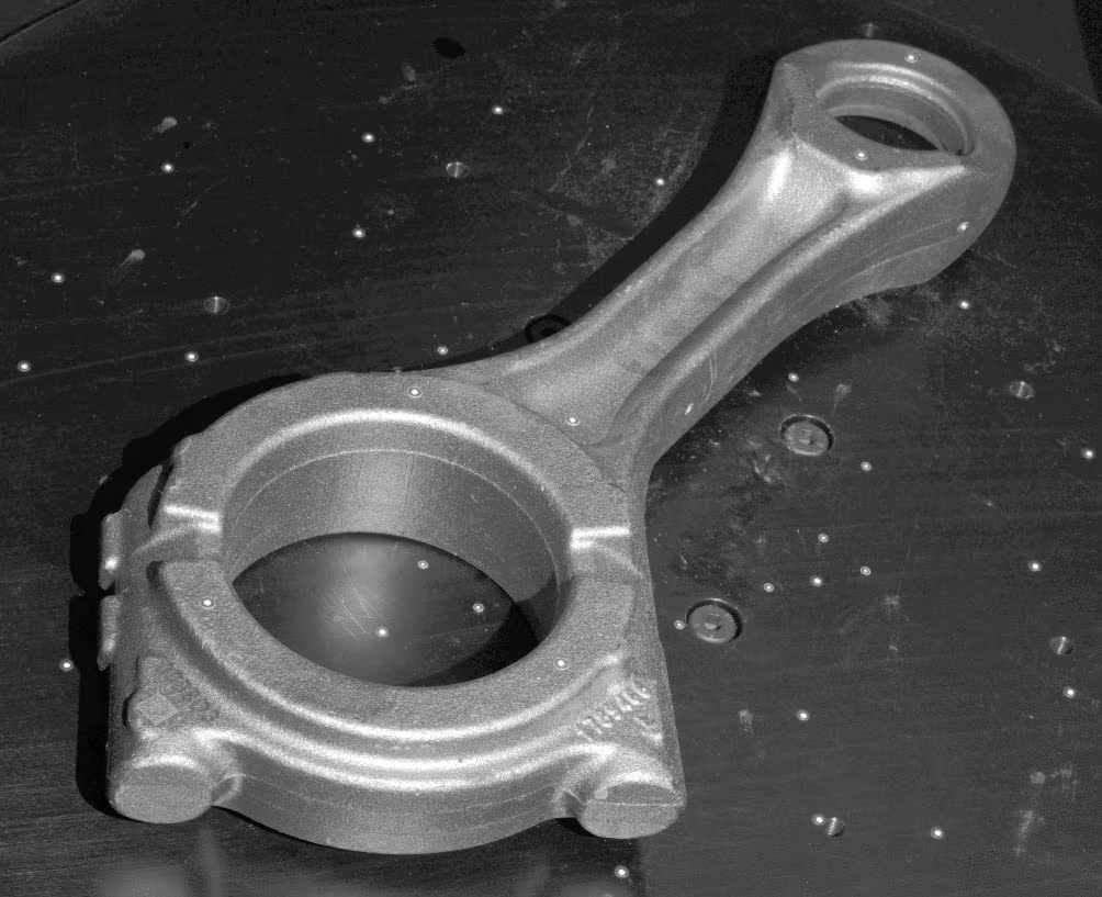
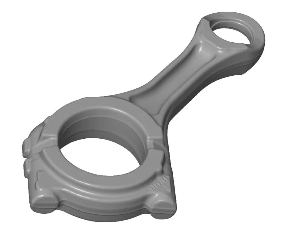
3D Scan results
The screenshots below show the final mesh and reverse engineering CAD model.

Free example data download
Feel free to download our scan and check the quality for yourself.
The stl file is packaged in a zip file, so you will need to unzip it before you can view the file.
RE_Crankshaft_Auto Surface_igs
.zip – size: 12.3 MB
RE_Crankshaft_Auto Surface_stp
.zip – size: 11.9 MB
RE_Crankshaft_Auto Surface_x_t
.zip – size: 10.5 MB
Scan_Crankshaft
.stl – size: 21.3 MB
For viewing our analysis and other scans in 3D, we recommend the free ZEISS Inspect software.