Scanning in combination with Reverse Engineering
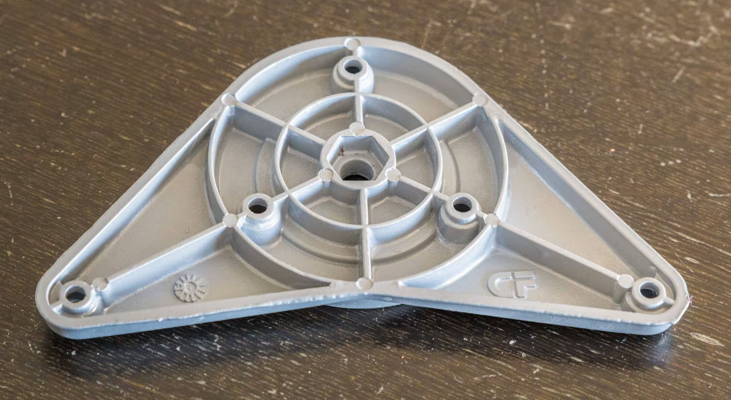
To reproduce this part, we made an optical 3D scan and used it as a reference for reverse engineering a new CAD model.
We used a geometric modelling approach.


Process: step by step
Process
- Spraying of the part with water based anti-reflex spray
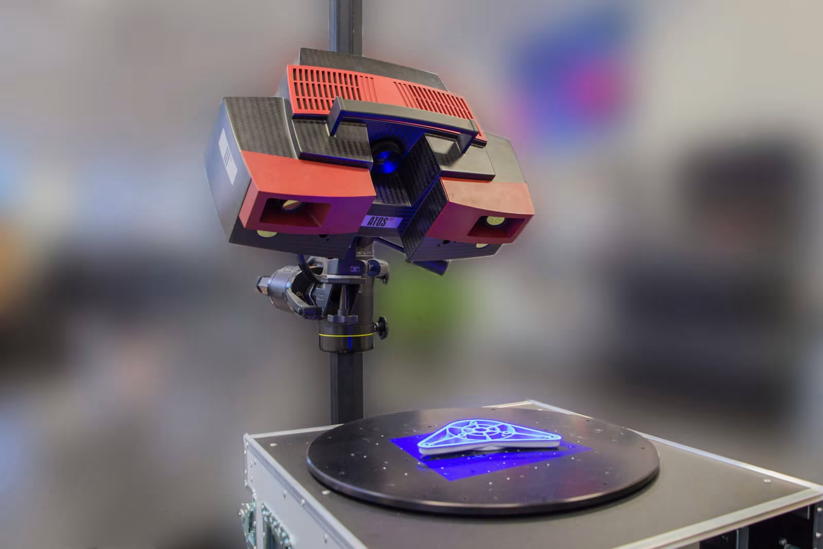
- Scanning in “free state”.
- Digitizing of the top and bottom
Technology
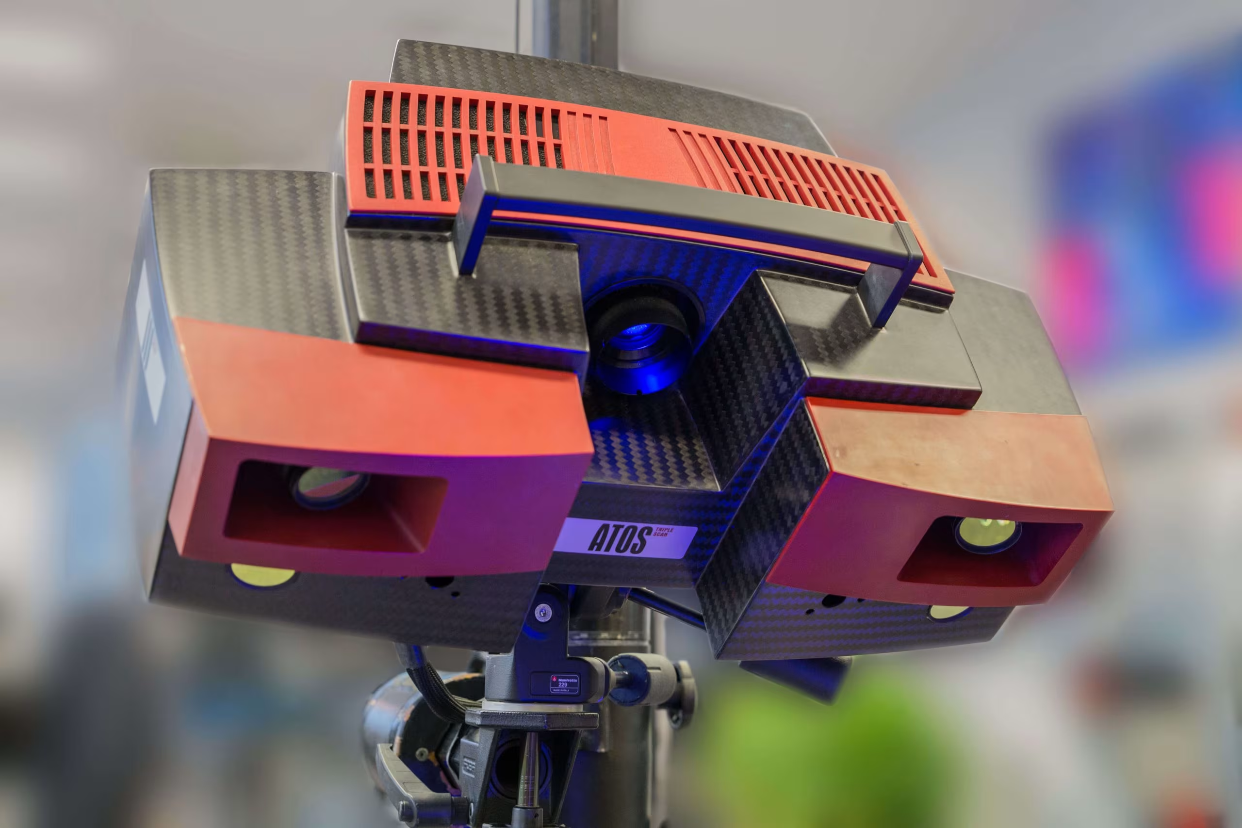
- GOM Atos III Triple scan with a 320MV (measuring volume)
- Automatic rotation table
Post-processing
- Alignment in the world coordinate system using the main features of the part.
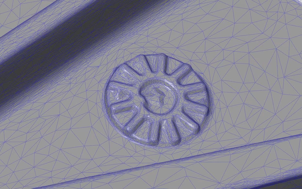
3D Scan results
The screenshots below show the final mesh and the reverse engineering CAD model


Free example data download
Feel free to download our scan and check the quality for yourself.
The stl file is packaged in a zip file, so you will need to unzip it before you can view the file.
TetraVision_Example_Casted Metal Part
.zip – size: 7.9 MB
For viewing our analysis and other scans in 3D, we recommend the free ZEISS Inspect software.